Laser wafer cutting equipment

A technology for cutting equipment and wafers, applied in laser welding equipment, welding equipment, metal processing equipment, etc., can solve problems such as parts installation and assembly errors, pollution of cutting head optical lenses, and affecting cutting accuracy, so as to eliminate assembly errors, The effect of avoiding optical path deviation and reducing production and maintenance costs

Pending Publication Date: 2021-10-15
SHANGHAI INST OF LASER TECH
View PDF0 Cites 3 Cited by
  • Summary
  • Abstract
  • Description
  • Claims
  • Application Information

AI Technical Summary

Problems solved by technology

However, the existing laser cutting equipment has optical path deviation caused by structural deformation during the processing process, which affects the cutting accuracy and causes errors in parts installation and assembly.
At the same time, the optical lens of the cutting head will be polluted during the cutting process

Method used


Image

  • Laser wafer cutting equipment
  • Laser wafer cutting equipment
  • Laser wafer cutting equipment

Examples


Embodiment Construction

[0026] The present invention will be further described in detail below in conjunction with the accompanying drawings and specific embodiments. According to the following description, the purpose, technical solution and advantages of the present invention will be more clear. It should be noted that the described embodiments are preferred embodiments of the present invention, but not all embodiments.

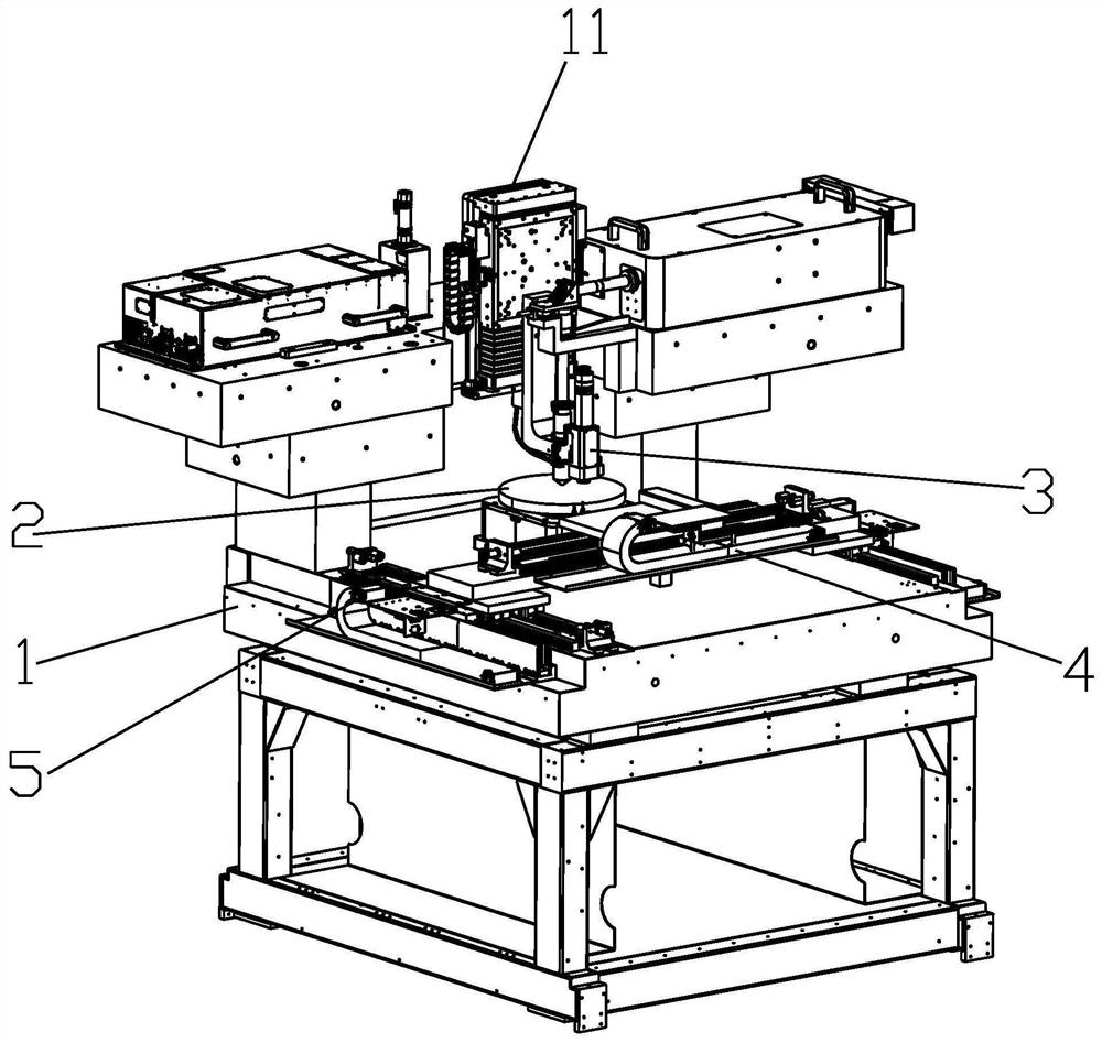
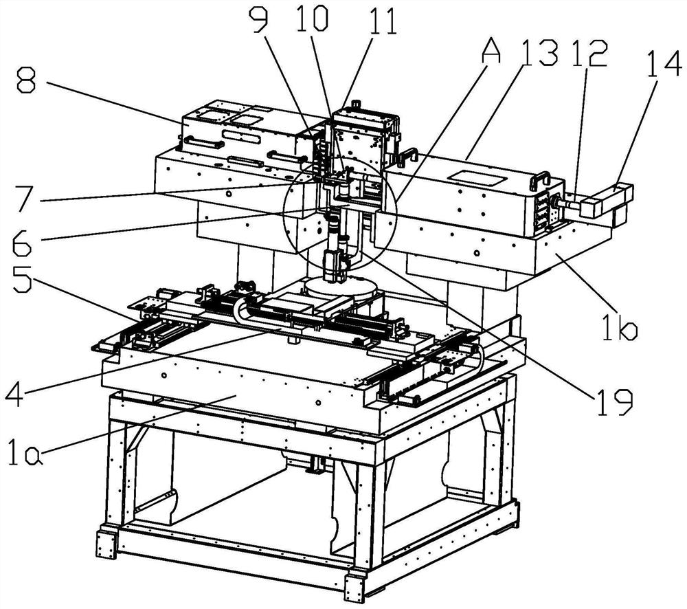
[0027] combine figure 1 , figure 2 As shown, a laser wafer cutting equipment includes a marble platform 1, an air flotation platform 2, an X-axis motion mechanism 4, a Y-axis motion mechanism 5, a Z-axis linear motor 11, a bracket 6, a slide table 7, a laser 8, and an installation Board 9, 45-degree mirror optical path assembly 10, beam splitting system 13, 45-degree mirror optical path assembly 14, cutting head 16 and cutting head support 19. The marble platform 1 includes a primary platform 1a and a secondary platform 1b arranged on the primary platform 1a. Please combine ...


PUM


Abstract

The invention relates to laser wafer cutting equipment which comprises a marble platform, an air floating platform, an X-axis movement mechanism, a Y-axis movement mechanism, a Z-axis linear motor, a support, a sliding table, a laser, a mounting plate, a 45-degree mirror light path assembly, a light splitting system, a 45-degree mirror light path assembly, a cutting head and a cutting head support. The marble platform comprises a first-stage platform and a second-stage platform arranged on the first-stage platform. According to the invention, the linear motors are mounted in the X-axis direction, the Y-axis direction and the Z-axis direction, so that operation can be guaranteed to be carried out at the micrometer precision. The support is mounted on the second-stage platform of the marble platform; the sliding table is mounted on the support; fine adjustment in the x direction can be implemented through the sliding table so as to ensure that a light path is accurate. The second-stage platform is integrally machined, and the overall rigidity is good, so that light path deviation caused by support deformation is avoided, and the situation that the light path is difficult to adjust due to flatness errors is avoided. up-and-down movement can be carried out in the Z-axis direction to adjust and position, thereby eliminating assembly errors in the optical path height.

Description

technical field [0001] The invention relates to laser wafer cutting equipment, which belongs to the technical field of wafer cutting. Background technique [0002] The earliest wafers were cut with a scribing system, one was through the scribing method and the diamond scribing method; the other was the saw method (cutting method), and the appearance of thick wafers made the saw method the first choice for the scribing process . Since the edge of the chip drawn by the saw blade method (cutting method) is better, and there are fewer cracks and chipping on the side of the chip, this method still occupies a large share of the world's chip cutting market, especially in non-integrated circuits. In the field of wafer dicing, diamond saw blade dicing is currently the most common method. However, since cutting is a mechanical force directly acting on the surface of the wafer, stress damage will occur inside the crystal. It has certain limitations. For wafers with a thickness below...

Claims


Application Information

Patent Timeline
Patent Type & Authority Applications(China)
IPC IPC(8): B23K26/02B23K26/14B23K26/142B23K26/38B23K26/70
CPCB23K26/38B23K26/142B23K26/14B23K26/02B23K26/702
Inventor 罗海燕王丽汪于涛骆公序董岿然
Owner SHANGHAI INST OF LASER TECH
Why Eureka
Try Eureka