Optical fiber grinding machine

A grinding machine and optical fiber technology, which is applied in grinding machine tools, grinding devices, grinding machine parts, etc., can solve the problem of increased labor intensity of operators, and achieve the effect of improving connection stability, reducing standby time, and reducing labor intensity.

Active Publication Date: 2021-10-15
SHENZHEN ADTEK TECH CO LTD
View PDF7 Cites 0 Cited by
  • Summary
  • Abstract
  • Description
  • Claims
  • Application Information

AI Technical Summary

Problems solved by technology

[0004] In view of the above-mentioned related technologies, the inventor believes that when polishing the end faces of optical fibers in batches, the operator needs to continuously and repeatedly complete the pick-and-place and fixation of the optical fiber chuck, which increases the labor intensity of the operator

Method used


Image

  • Optical fiber grinding machine
  • Optical fiber grinding machine
  • Optical fiber grinding machine

Examples


Embodiment Construction

[0041] The following is attached Figure 1-6 The application is described in further detail.

[0042] The embodiment of the present application discloses an optical fiber polishing machine.

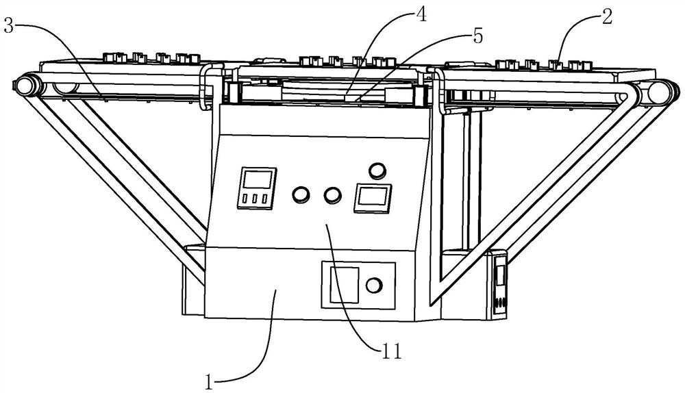
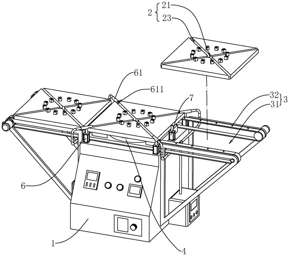
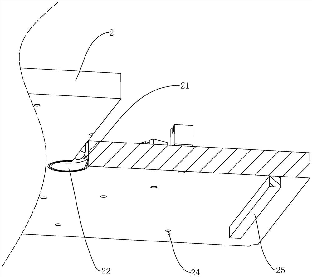
[0043] refer to figure 1 , figure 2 , the optical fiber polishing machine includes a base 1, a plurality of optical fiber chucks 2 inserted with optical fibers, and a delivery track 3 for transporting a plurality of optical fiber chucks 2, the delivery track 3 is rotatably connected to the base 1, and the delivery track The feeding surface of 3 is parallel to the top of support 1. The feeding track 3 has elasticity, and the feeding track 3 is a rubber conveyor belt driven by a motor. A plurality of optical fiber chucks 2 are arranged at intervals on the surface of the delivery track 3 along the length direction of the delivery track 3 . The top end of the base 1 is provided with a grinding disc 4 for contacting the end face of the optical fiber, and the base 1 is provided with a rot...


PUM


Abstract

The invention relates to the field of optical fiber grinding devices, in particular to an optical fiber grinding machine. The machine comprises a machine base, a plurality of optical fiber chucks provided with optical fibers in an inserted mode and a material conveying rail used for conveying the optical fiber chucks; the top end of the machine base is provided with a grinding disc used for abutting against the end surfaces of the optical fibers; the grinding disc is located in the middle of the material conveying rail; the machine base is provided with at least two telescopic air cylinders; the at least two telescopic air cylinders are located on the two sides of the material conveying rail correspondingly; abutting blocks are arranged at the ends of piston rods of the telescopic air cylinders; the side walls of the abutting blocks and the end surface, opposite to the machine base, of barrels of the telescopic air cylinders abut against the opposite surfaces of the optical fiber chucks correspondingly. Compared with the situation that an operator needs to continuously and repeatedly take, place and fix the optical fiber chucks, the machine has the advantages that after the operator places the multiple optical fiber chucks on the material conveying rail, all that is required for completing the operation that the multiple optical fiber chucks are oppositely placed and fixed relative to the grinding disc in turn is to open and close the material conveying rail and the telescopic air cylinders, and the machine has the effect of reducing the labor intensity of the operator.

Description

technical field [0001] The present application relates to the field of optical fiber polishing devices, in particular to an optical fiber polishing machine. Background technique [0002] Optical fiber is the most basic and important part of optical communication. The word optical fiber is the abbreviation of optical fiber. When the optical signal is transmitted through the end face of the optical fiber, due to refraction or some reasons, part of the optical energy will be attenuated, which is the transmission loss of the optical fiber, so the effect of optical fiber end face grinding is very important. In order to allow better contact between the end faces of the two optical fibers, the ferrule end faces of fiber optic jumpers are usually ground into different structures using a fiber optic grinder. [0003] The optical fiber polishing machine mainly includes a machine base, a grinding disc set in the middle of the top of the machine base, an optical fiber chuck set above t...

Claims


Application Information

Patent Timeline
Patent Type & Authority Applications(China)
IPC IPC(8): B24B37/10B24B37/30B24B37/34B24B47/12B24B55/00B24B53/017B24B19/22
CPCB24B37/10B24B37/30B24B37/345B24B37/34B24B47/12B24B55/00B24B53/017B24B19/226
Inventor 马奎李宝荣余振龙
Owner SHENZHEN ADTEK TECH CO LTD
Why Eureka
Try Eureka