Real-time displacement measurement method based on monocular camera

A monocular camera and displacement measurement technology, which is applied in image enhancement, image analysis, image data processing, etc., can solve the problems of unstable measurement at night and low measurement accuracy

Inactive Publication Date: 2021-10-15
ANHUI UNIV OF SCI & TECH
View PDF4 Cites 0 Cited by
  • Summary
  • Abstract
  • Description
  • Claims
  • Application Information

AI Technical Summary

Problems solved by technology

However, the displacement measurement technology based on this principle also has the disadvantages of low measurement accuracy and unstable measurement at night

Method used


Image

  • Real-time displacement measurement method based on monocular camera
  • Real-time displacement measurement method based on monocular camera
  • Real-time displacement measurement method based on monocular camera

Examples


Embodiment 1

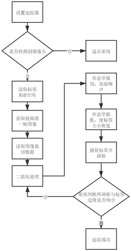
[0045] Embodiment 1: In order to better illustrate the present invention, a kind of real-time displacement measurement method based on monocular camera, the present invention comprises the following steps:

[0046] (1) Check the measurement environment and paste specific labels;

[0047] (2) Enter the measurement system, check the camera data, if not detected, exit the system;

[0048] (3) Obtain the first frame image taken by the camera, read the cutting data of the system and cut the picture;

[0049] (4) Read the RGB value space of the system preset label, perform binarization on the cropped image, further remove noise through morphological operations such as corrosion and expansion, and obtain a clear and complete label and capture its edge.

[0050] (5) Initialize the label coordinates of the first frame obtained in the previous step, then start the timer to read the new frame, frame the label on the image,

[0051] (6) Observe whether the frame is equal in size to the ...

Embodiment 2

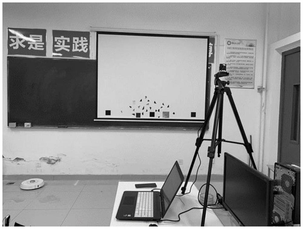
[0053] Embodiment 2: In order to better illustrate the present invention, we simulate measuring the displacement of a projector screen in a daytime environment. The present invention comprises the following steps:

[0054] (1) Paste specific labels on the projector screen, determine the location of the camera layout, and the final environment layout results are as follows figure 2 shown.

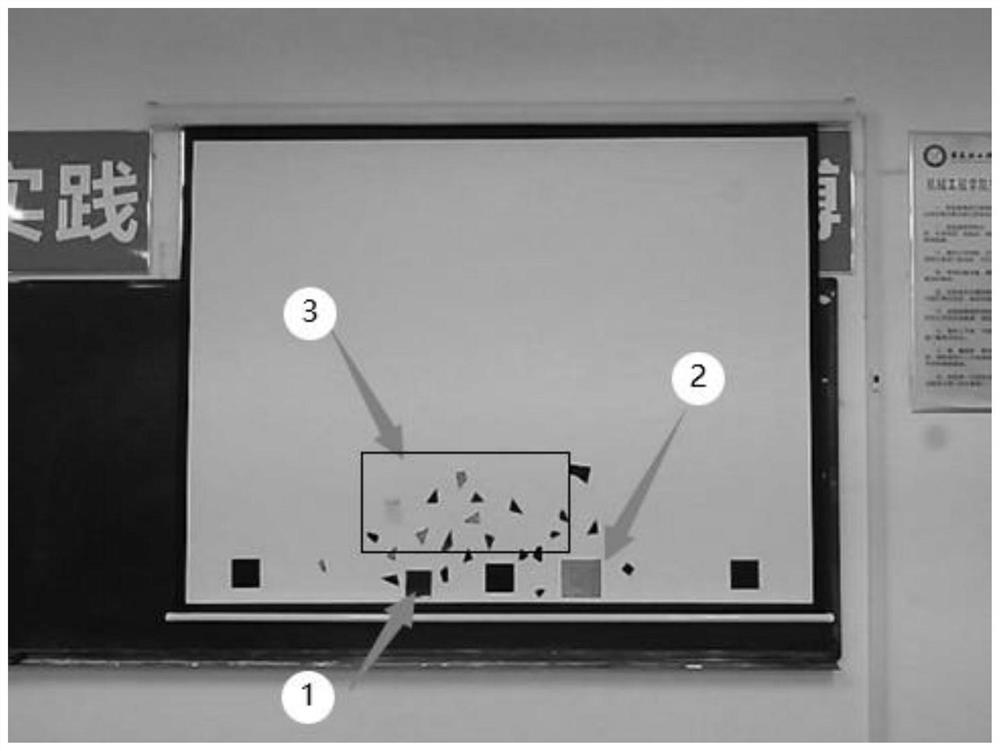
[0055] (2) Enter the system, turn on the camera to obtain image 3 In the first frame of the image shown, the part ① in the illustration is a specific label, and the other part ②③ is a colored interference sticker, which simulates the interference of environmental objects on the system and verifies the stability of system recognition.

[0056] (3) In order to prevent the interference of objects with large areas and similar RGB values ​​in the environment in the picture, it is first necessary to read the preset cropping data in the system to crop the disturbing objects in the first frame of...

Embodiment 3

[0065] Embodiment 3: In order to better illustrate the present invention, we simulate measuring the displacement of a projector screen in a nighttime environment. The present invention comprises the following steps:

[0066] (1) Paste specific labels on the projector screen, determine the location of the camera, and arrange the infrared fill light. The final environment layout results are as follows: Figure 7 shown.

[0067] (2) Enter the system, turn on the camera to obtain Figure 8 The first frame image shown.

[0068] (3) In order to prevent the interference of objects with large areas and similar RGB values ​​in the environment in the picture, it is first necessary to read the preset cutting data in the system to cut the interference objects in the first frame of the above step (2). After cutting, the image is as follows Figure 8 .

[0069] (4) Read the RGB value space of the system’s preset label, and use the Kittle algorithm to binarize the cropped image in step ...


PUM


Abstract

The invention discloses a real-time displacement measurement method based on a monocular camera. The method comprises the steps that firstly, a monocular camera arrangement position and a label pasting position are determined according to a measurement environment; the monocular camera is utilized to identify, capture and frame-select a specific label and to calculate the height of a rectangular frame; when the label moves, a tracker is used for tracking the label, the actual movement distance of the label is calculated according to the proportional relation between the height of the rectangular frame in the actual environment and the height of the rectangular frame captured by the monocular camera, and the displacement of the label is displayed in real time; and when real-time displacement measurement is carried out on the label in a night environment, the displacement measurement is carried out on the label by using a night camera carrying an infrared light supplementing module. According to the method provided by the invention, a monocular vision displacement measurement mode is effectively optimized, and stable measurement in a non-contact and night environment is realized.

Description

technical field [0001] The invention discloses a real-time displacement measurement method based on a monocular camera. Background technique [0002] Linear displacement measurement is widely used in various fields of industrial production. At present, the measurement method based on the principle of time grating displacement sensor and laser sensor is more commonly used. It has high measurement accuracy and reliable operation, but its installation and debugging process is complicated and expensive. [0003] With the rapid development of related technologies such as computer vision, artificial intelligence, and image processing, displacement measurement technology based on machine vision has gradually attracted attention due to its advantages of low cost and non-contact measurement. However, the displacement measurement technology based on this principle also has the disadvantages of low measurement accuracy and unstable measurement at night. [0004] The key technology of ...

Claims


Application Information

Patent Timeline
Patent Type & Authority Applications(China)
IPC IPC(8): G06T7/246G06T5/30G06T7/11G06T7/13G06T7/155G06T7/90
CPCG06T7/246G06T7/11G06T7/13G06T7/155G06T7/90G06T5/30G06T2207/10016
Inventor 储汇宋陈汪晨灿
Owner ANHUI UNIV OF SCI & TECH
Why Eureka
Try Eureka