
Processing equipment with heat resistance detection function for cooling fins of electric oil heaters

A technology for processing equipment and heat sinks, which is applied in the field of processing equipment for heat resistance detection of electric heat sinks, can solve problems such as inability to ensure product appearance, consistent stamping dimensions, product defects, etc., to improve detection efficiency and product quality , to avoid position mismatch, to avoid the effect of not being able to weld

Pending Publication Date: 2021-10-22
重庆惠迈锐智能装备科技有限公司
View PDF0 Cites 0 Cited by
  • Summary
  • Abstract
  • Description
  • Claims
  • Application Information

AI Technical Summary

Problems solved by technology

[0004] Aiming at the deficiencies of the prior art, the present invention provides a processing equipment for heat resistance detection of electric oil heat sinks, which solves the problem that the general electric oil heat sink processing equipment proposed in the above background technology generally adopts manual stamping, The welding processing method and manual stamping cannot ensure the appearance and stamping size of the product are consistent, resulting in product defects, and are generally inspected after the product is assembled, which is likely to cause waste of resources

Method used


Image

  • Processing equipment with heat resistance detection function for cooling fins of electric oil heaters
  • Processing equipment with heat resistance detection function for cooling fins of electric oil heaters
  • Processing equipment with heat resistance detection function for cooling fins of electric oil heaters

Examples


Embodiment Construction

[0030] The technical solutions in the embodiments of the present invention will be clearly and completely described below in conjunction with the accompanying drawings in the embodiments of the present invention. Obviously, the described embodiments are only some of the embodiments of the present invention, not all of them. Based on The embodiments of the present invention and all other embodiments obtained by persons of ordinary skill in the art without making creative efforts belong to the protection scope of the present invention.

[0031] In the description of the present invention, unless otherwise stated, the meaning of "plurality" is two or more; the terms "upper", "lower", "left", "right", "inner", "outer" , "front end", "rear end", "head", "tail", etc. indicate the orientation or positional relationship based on the orientation or positional relationship shown in the drawings, and are only for the convenience of describing the present invention and simplifying the desc...


PUM


Abstract

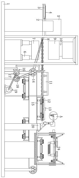
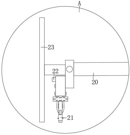
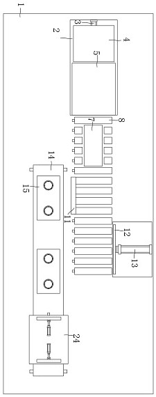
The invention discloses processing equipment with a heat resistance detection function for cooling fins of electric oil heaters. The processing equipment with the heat resistance detection function for the cooling fins of the electric oil heaters comprises a chassis, wherein a material placing plate is arranged above the left of the chassis; a material pushing plate is arranged on the right of a material pushing rod; a lifting rod is arranged on the right of a material storage bin; multiple rolling shafts are arranged above a male die; a hydraulic rod is arranged above a female die; a turnover mechanism is arranged in the middles of the rolling shafts; a pushing plate is arranged behind the rolling shafts; a conveying belt is arranged in front of the turnover mechanism; a bevel gear is arranged below the conveying belt; a full gear is arranged on the right part of a half gear; a mechanical arm is arranged on the right part of a motor; and a positioning instrument is arranged on the left side of a welding machine. Compared with existing common processing equipment for the cooling fins of the electric oil heaters, the processing equipment with the heat resistance detection function for the cooling fins of the electric oil heaters has the advantages that the heat resistance of a product can be detected, the injury to a user caused by thermal deformation and even bursting of the product in the use process is avoided, and the processing efficiency and the processing quality of the product are improved.

Description

technical field [0001] The invention relates to the technical field of processing heat sinks of electric oil heaters, in particular to a processing equipment for heat resistance detection of electric oil heat sinks. Background technique [0002] Electric oil heating heater, referred to as electric heating oil heater, is an oil-filled heater. It is a safe and reliable space heater popular in recent years. It is mainly composed of sealed electric heating elements, metal heating tubes, iron radiators, control The heating element, power switch, indicator light, etc., and the heat sink is a very important part, which can dissipate the internal heat to heat up the room. [0003] Existing heat sink processing equipment generally adopts manual stamping and welding processing methods. Manual stamping cannot ensure that the appearance and stamping size of the product are consistent, resulting in product defects, and the inspection is generally performed after the product is assembled....

Claims


Application Information

Patent Timeline
Patent Type & Authority Applications(China)
IPC IPC(8): B21D43/02B21D43/09B21D45/06B21D43/11B21D43/14B21D43/00B21D22/02B21D53/04B21D37/10B23K37/04B07C5/342B07C5/02B07C5/36B23P23/00
CPCB21D43/026B21D43/027B21D43/09B21D45/06B21D43/11B21D43/145B21D43/003B21D22/02B21D53/04B21D37/10B23K37/0408B07C5/3422B07C5/02B07C5/362B23P23/00B07C2501/0063
Inventor 葛珺谢怀恩杨珺函
Owner 重庆惠迈锐智能装备科技有限公司
Learn More