
Coupling treatment device for circulating water

A treatment device and circulating water technology, applied in water/sewage multi-stage treatment, water/sludge/sewage treatment, magnetic field/electric field water/sewage treatment, etc. Problems such as fouling of the device can be solved to meet the process requirements, improve the heat exchange efficiency and facilitate the discharge.

Pending Publication Date: 2021-10-22
汉德森工业装备(北京)有限公司
View PDF0 Cites 1 Cited by
  • Summary
  • Abstract
  • Description
  • Claims
  • Application Information

AI Technical Summary

Problems solved by technology

[0003] During the use of the heat exchanger, its internal structure is generally more complicated, so it is easy to have a large active surface
When the heat exchanger is used for a long time, especially when the heat exchange temperature difference of the heat exchanger is large, the circulating water is very easy to precipitate calcium and magnesium substances, which will make the inside of the heat exchanger foul, which will directly affect the heat exchange efficiency.
In the prior art, the fouling phenomenon of the heat exchanger cannot be solved well, and regular descaling treatment is often required. In this process, affected by the cost of the heat exchanger equipment, etc., it is often directly shut down for descaling processing, resulting in higher maintenance costs
[0004] Moreover, the water used by some heat exchangers in the utilization of circulating water is not clean. In addition to more calcium and magnesium ions, there are often impurities such as bacteria and algae. Facing the heat exchanger with a single treatment method , it is also necessary to remove algae and other substances, which greatly affects the actual use of heat exchangers

Method used


Image

  • Coupling treatment device for circulating water
  • Coupling treatment device for circulating water

Examples


Embodiment Construction

[0024] The following will clearly and completely describe the technical solutions in the embodiments of the present invention with reference to the accompanying drawings in the embodiments of the present invention. Obviously, the described embodiments are only some, not all, embodiments of the present invention. Based on the embodiments of the present invention, all other embodiments obtained by persons of ordinary skill in the art without making creative efforts belong to the protection scope of the present invention.

[0025] In the description of the present invention, it should be noted that the terms "upper", "lower", "inner", "outer", "front end", "rear end", "both ends", "one end", "another end" The orientation or positional relationship indicated by etc. is based on the orientation or positional relationship shown in the drawings, which is only for the convenience of describing the present invention and simplifying the description, rather than indicating or implying tha...


PUM


Abstract

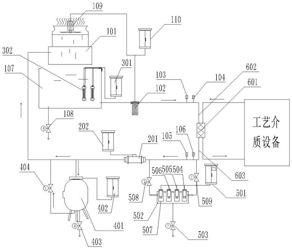
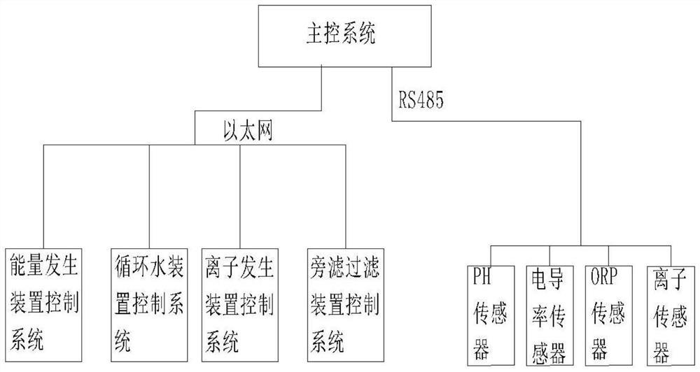
The invention discloses a coupling treatment device for circulating water. The coupling treatment device comprises industrial medium equipment, a heat exchanger installed through a medium pipeline, a liquid outlet pipe and a liquid inlet pipe, the liquid outlet pipe and the liquid inlet pipe are installed on the heat exchanger, a circulating water pump is installed at the tail end of the liquid inlet pipe, and an ion generating mechanism is installed at the input end of the circulating water pump through a pipeline. A circulating water mechanism is installed on the ion generating mechanism, a main control system mechanism is installed on the surface of the liquid outlet pipe through a pipeline bypass system, an energy generating mechanism is installed at the tail end of the liquid outlet pipe and connected with the circulating water mechanism through a circulating pipeline, and a bypass system filtering mechanism is arranged on the bypass of the circulating pipeline. By arranging a series of structures, the coupling treatment device for the circulating water can separate out calcium, magnesium and other ions in water in advance, scaling and algae or bacterium breeding in a heat exchanger are avoided, pollution discharge treatment is facilitated, the quality of the circulating water is improved, and the heat exchange efficiency is improved.

Description

technical field [0001] The invention relates to the technical field of energy-saving and environment-friendly water treatment, in particular to a coupling treatment device for circulating water. Background technique [0002] As a device that transfers part of the heat of the hot fluid to the cold fluid, the heat exchanger is actually widely used in various fields, especially in some metallurgical factories, which can cool the water body or recycle the waste heat, so it is often used as a Conventional production equipment is used. [0003] During the use of the heat exchanger, its internal structure is generally more complicated, so it is easy to have a large action surface. When the heat exchanger is used for a long time, especially when the heat exchange temperature difference of the heat exchanger is large, calcium and magnesium substances are easily precipitated in the circulating water, which in turn causes fouling inside the heat exchanger, which directly affects the h...

Claims


Application Information

Patent Timeline
Patent Type & Authority Applications(China)
IPC IPC(8): C02F9/12F28F19/00F28F19/01
CPCC02F9/00F28F19/00F28F19/01C02F5/02C02F1/50C02F1/48C02F1/001
Inventor 徐相旺王广江姬会东
Owner 汉德森工业装备(北京)有限公司
Learn More