
Ballastless track base plate post-cast strip bilateral breaking device, system and method

A ballastless track and base plate technology, applied in tracks, track maintenance, track superstructure and other directions, can solve the problems of low removal efficiency, inability to move left and right, low efficiency, etc., to improve removal efficiency, reduce operators, and achieve automation. high effect

Active Publication Date: 2021-10-22
SICHUAN SOUTHWEST JIAOTONG UNIV RAILWAY DEV
View PDF6 Cites 0 Cited by
  • Summary
  • Abstract
  • Description
  • Claims
  • Application Information

AI Technical Summary

Problems solved by technology

[0006] However, the high-pressure nozzle of the breaking device can move back and forth and up and down, but cannot move left and right
In actual operation, since the nozzle of the device cannot move left and right, when it is necessary to remove the entire lateral area of ​​the post-casting belt, it is necessary to unlock the lateral locking mechanism of the device, and then remove the device after the overall translation and locking , this process requires pressure relief or shutdown, the process is complicated, the efficiency is low, and it does not have the sweeping and breaking function, so the device cannot break the concrete in the post-pouring belt in all directions; at the same time, the breaking device is integral, and it needs to be transported It is time-consuming and labor-intensive for multiple people to carry it to the work site as a whole; in addition, the removal device can only remove the rear cast belt of the ballastless track base plate from one side, and the removal efficiency is low

Method used


Image

  • Ballastless track base plate post-cast strip bilateral breaking device, system and method
  • Ballastless track base plate post-cast strip bilateral breaking device, system and method
  • Ballastless track base plate post-cast strip bilateral breaking device, system and method

Examples


Embodiment 1

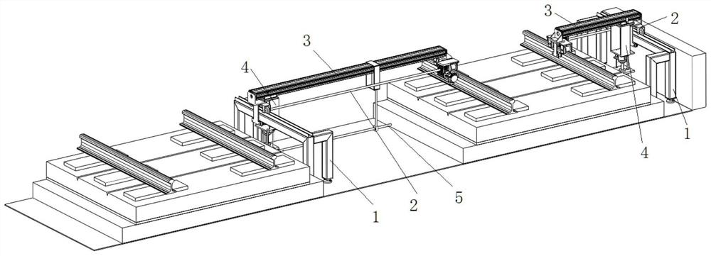
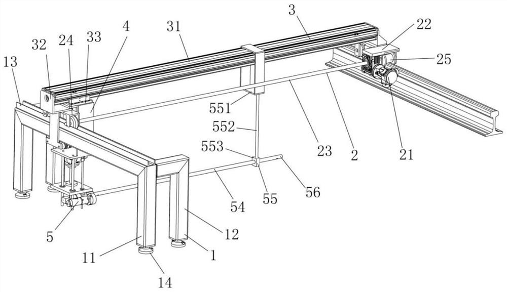
[0066] A double-sided breaking device for the post-casting belt of the ballastless track base plate, such as figure 1 and 2 shown, including:

[0067] Rack 1;

[0068] Left and right moving mechanism 2, one end is slidable and detachably mounted on the frame 1, and the other end is slidable and detachably mounted on the railway rail;

[0069] The front and rear moving mechanism 3 is detachably installed on the left and right moving mechanism 2;

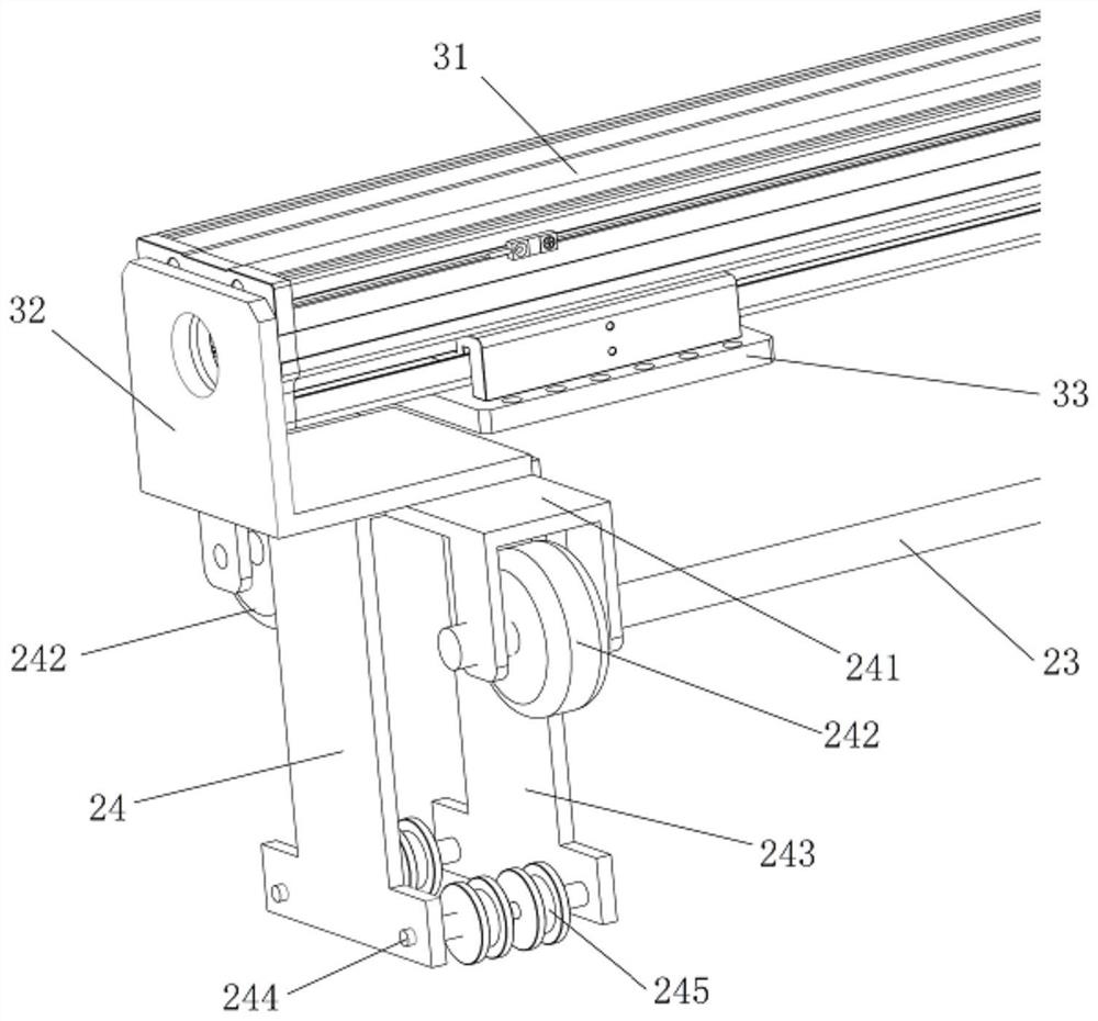
[0070] The lifting mechanism 4 is detachably installed on the output end of the forward and backward moving mechanism 3;

[0071] Rotating breaking mechanism 5 is installed on the output end of lifting mechanism 4, and is driven by left and right moving mechanism 2, forward and backward moving mechanism 3 and lifting mechanism 4 to realize left and right, front and rear and up and down movement, and its front end is equipped with high pressure nozzle 56.

[0072] In this embodiment, the frame 1 is used to install the left and righ...

Embodiment 2

[0108] A double-sided breaking system for post-casting belts of ballastless track base plates, such as Figure 7 shown, including:

[0109] The water tank 61 is equipped with a water source for pressurization;

[0110] A high-pressure water pump 62, its water inlet end is connected to the water tank 61 through a water pipe, and the water in the water tank 61 is pressurized to become high-pressure water;

[0111] In the breaking device in embodiment 1, the water inlet end of the rotating breaking mechanism 5 of the breaking device is connected to the water outlet end of the high-pressure water pump 62 through a high-pressure water pipe, and the high-pressure water enters the rotating breaking mechanism 5 and then rotates and sprays out, and casts the belt after breaking;

[0112] The gas supply station 63 is connected to the left and right moving mechanism 2, the front and rear moving mechanism 3, and the rotating breaking mechanism 5 of the breaking device, and supplies air t...

Embodiment 3

[0116] A method for breaking both sides of the post-cast belt of a ballastless track base plate, comprising the following steps:

[0117] S1. Move each component of the breaking device to the side of the rear casting belt of the base plate of the ballastless track in pieces.

[0118] Specifically, the frame 1, the left and right moving mechanism 2, the front and rear moving mechanism 3, the lifting mechanism 4 and the rotating breaking mechanism 5 can be manually transported to the side of the back casting belt of the ballastless track base plate several times.

[0119] S2. Assemble two breaking devices, so that the two breaking devices are respectively installed on the two sides of the rear casting belt of the base plate of the ballastless track.

[0120] Such as figure 1 As shown, two breaking devices are assembled on both sides of the post-casting belt of the ballastless track base plate. According to the actual working space, the left and right moving mechanism 2 and the ...


PUM


Abstract

The invention discloses a ballastless track base plate post-cast strip bilateral breaking device, system and method. The breaking device comprises a rack, a left-right moving mechanism, a front-back moving mechanism, a lifting mechanism and arotary breaking mechanism, wherein one end of the left-right moving mechanism is slidably and detachably mounted on the rack, and the other end of the left-right moving mechanism is slidably and detachably mounted on a railway steel rail; the front-back moving mechanism is detachably mounted on the left-right moving mechanism; the lifting mechanism is detachably mounted at the output end of the front-back moving mechanism; the rotary breaking mechanism is installed at the output end of the lifting mechanism and driven by the left-right moving mechanism, the front-back moving mechanism and the lifting mechanism to move left and right, front and back and up and down, and a high-pressure spray head is installed at the front end of the rotary breaking mechanism. The breaking device is in a block type, so that the breaking device can be conveniently carried to a working site in a block manner for installation, and operators required for carrying are reduced; the left-right moving mechanism and the front-back moving mechanism with proper lengths can be selected, and the breaking device is mounted on the two side surfaces of the ballastless track base plate post-cast strip, so that the post-cast strip is broken from the two sides, and the breaking efficiency is improved.

Description

technical field [0001] The invention relates to the field of equipment for concrete removal, in particular to a device, system and method for removing both sides of a post-cast belt of a ballastless track base plate. Background technique [0002] Since the ballastless track on the bridge was laid on the Beijing-Tianjin Intercity Railway, because of its stability and comfort during high-speed operation, it has been successively laid on the Beijing-Shanghai High-speed Railway, Beijing-Wuhan High-speed Railway, Shanghai-Hangzhou Passenger Dedicated Line, and Nanjing-Hangzhou Passenger Dedicated Line , Hebang Passenger Dedicated Line, etc., have been widely used. The ballastless track system on the bridge is composed of steel rails, fasteners, track plates, mortar adjustment layers, base plates, two cloth and one film sliding layers, high-strength extruded plastic plates, and lateral stops. Friction plates, End thorns and transition plates. [0003] In order to solve the techn...

Claims


Application Information

Patent Timeline
Patent Type & Authority Applications(China)
IPC IPC(8): E01D24/00E01D19/12E01B37/00E01B1/00
CPCE01D22/00E01D19/12E01B37/00E01B1/002E01B2203/143E01B2204/09Y02W30/56
Inventor 王鹏翔秦奇黄为邹自良江源蒋维
Owner SICHUAN SOUTHWEST JIAOTONG UNIV RAILWAY DEV
Learn More