
Thermochemical heat storage system and method

A heat storage system and thermochemical technology, applied in the field of thermochemical heat storage system and heat storage, can solve the problems of waste of solar energy resources, waste of solar energy resources, and environmental hazards, etc., to reduce light abandonment, improve utilization rate, and improve energy storage The effect of thermal efficiency

Active Publication Date: 2021-10-22
ZHEJIANG UNIV
View PDF6 Cites 3 Cited by
  • Summary
  • Abstract
  • Description
  • Claims
  • Application Information

AI Technical Summary

Problems solved by technology

When the solar radiation is strongest at noon, the efficiency of photovoltaic power generation is the highest. Since solar thermal power generation needs to undertake the task of peak regulation, during this period, the photovoltaic power plant runs at full capacity while the solar thermal power plant stops generating power, which is the so-called "light abandonment". Cause a lot of waste of solar energy resources
Under such a policy background, solar thermal power plants store heat when the sun is strongest at noon, and convert solar energy into thermal energy and store it in molten salt. Some molten salt tower solar power plants that were originally designed have appeared. The storage tank is too small. All the molten salt absorbs solar radiation and the temperature rises and is stored in the high-temperature molten salt tank. There is no molten salt flowing through the heat absorber to absorb heat. In order to avoid the overheating of the heat absorber, it is necessary to Other places that reflect sunlight through heliostats not only waste a lot of solar energy resources, but also cause harm to the surrounding environment

Method used


Image

  • Thermochemical heat storage system and method
  • Thermochemical heat storage system and method
  • Thermochemical heat storage system and method

Examples


Embodiment approach 1

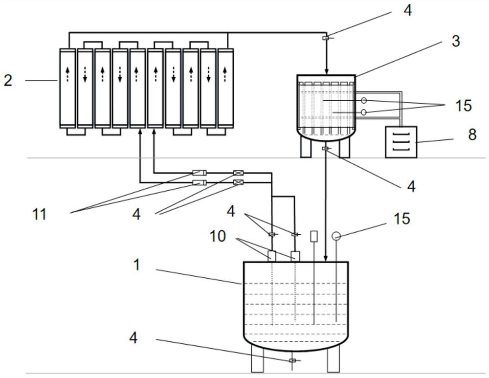
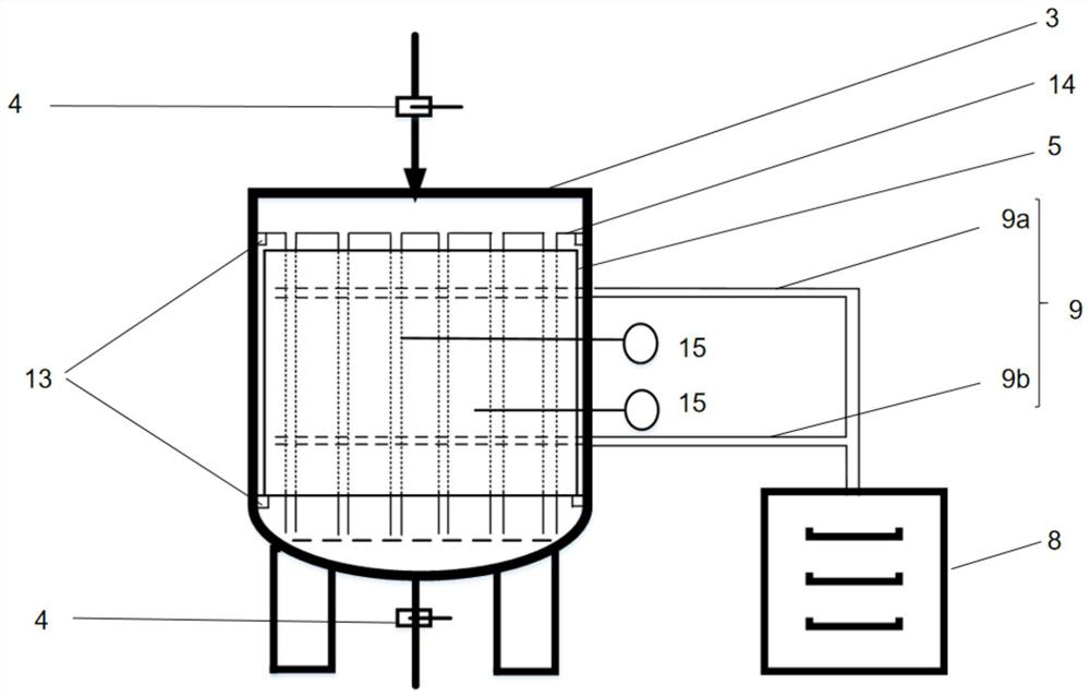
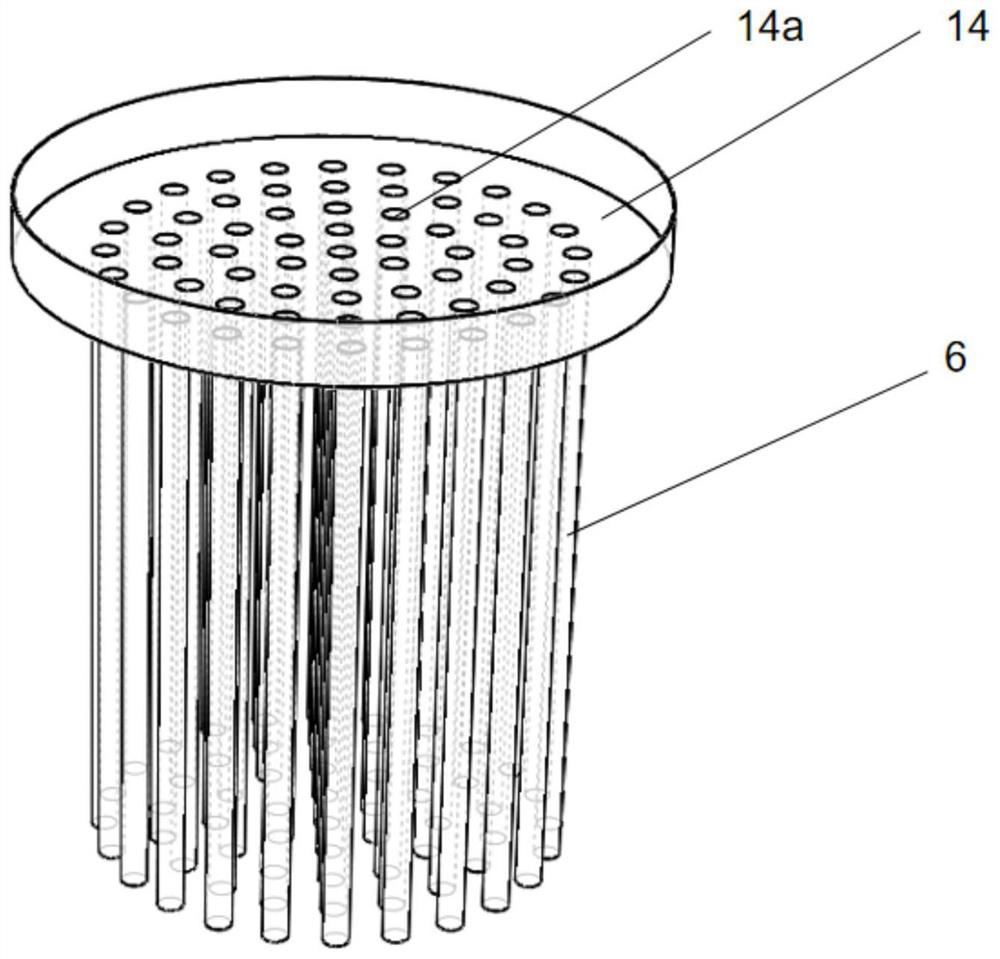
[0059] The first embodiment of the present invention provides a thermochemical heat storage system, see figure 1 and figure 2 As shown, it includes a low-temperature molten salt storage tank 1, a heat absorber 2, and a thermochemical molten salt storage tank 3 connected in sequence to form a circulation loop. Both the inlet and the outlet of the tank 3 are provided with valves 4 . The outlet of the low-temperature molten salt storage tank 1 communicates with the inlet of the heat absorber 2, the outlet of the heat absorber 2 communicates with the inlet of the thermochemical molten salt storage tank 3, and the outlet of the thermochemical molten salt storage tank 3 communicates with the low-temperature molten salt storage tank The entrance of 1 is connected. The exterior of the low-temperature molten salt storage tank 1 and / or the thermochemical molten salt storage tank 3 is wrapped with an insulating material (not shown) to reduce external heat dissipation of the low-temper...

Embodiment approach 2

[0085] The second embodiment of the present invention provides a thermochemical heat storage system. The second embodiment is a further improvement on the first embodiment. Parts not specifically described include reference numerals and text descriptions, which are the same as those of the first embodiment. The method is the same and will not be repeated here.

[0086] The main improvement of the second embodiment over the first embodiment is that in the second embodiment of the present invention, the combination Figure 6 From the point of view, the thermochemical heat storage system also includes a high-temperature molten salt storage tank 16. The inlet and outlet of the high-temperature molten salt storage tank 16 are connected with the outlet of the heat absorber 2 and the inlet of the low-temperature molten salt storage tank 1 respectively. The inlet and outlet of the storage tank 16 are also provided with valves 4 , and the high-temperature molten salt storage tank 16 an...

Embodiment approach 3

[0103] The third embodiment of the present invention provides a thermochemical heat storage system. The third embodiment is a further improvement on the second embodiment. Parts not specifically described include reference numerals and text descriptions, which are the same as those of the second embodiment. The method is the same and will not be repeated here.

[0104] The main improvement of the third embodiment over the second embodiment is that in the third embodiment of the present invention, the combination of Figure 8 From the point of view, the material of the thermochemical heat storage module is CaCO 3 / CaO or MgCO 3 / MgO, CaCO 3 / CaO or MgCO 3 / MgO can spontaneously decompose at high temperature to generate CaO and MgO, and absorb CO 2 And absorb a lot of heat, CaO and MgO can add CO 2 Afterwards, the recombination reaction occurs spontaneously to form CaCO 3 and MgCO 3 And release a lot of heat. The aforementioned evaporator 8 is replaced by CO 2 The stora...


PUM


Abstract

The invention relates to the technical field of solar thermal power generation, and discloses a thermochemical heat storage system and method. The thermochemical heat storage system comprises a low-temperature fused salt storage tank, a heat absorber and a thermochemical fused salt storage tank which are connected in sequence and form a circulation loop. The thermochemical fused salt storage tank is provided with a thermochemical reactor, a fused salt circulation pipeline is arranged in the thermochemical reactor, the thermochemical reactor is filled with a thermochemical heat storage module, and the thermochemical heat storage module can be subjected to the dehydration reaction at the high temperature and absorb heat. The thermochemical heat storage system is further provided with an evaporator and a reaction gas pipeline communicating with the evaporator and the thermochemical reactor. Fused salt flowing out of the low-temperature fused salt storage tank is heated in the heat absorber, then enters the thermochemical fused salt storage tank, exchanges heat with the thermochemical heat storage module and is used for the dehydration reaction of the thermochemical heat storage module, heat is stored in the thermochemical heat storage module in the form of chemical energy, the heat storage efficiency is improved, abandoned light is reduced, and the utilization rate of solar energy resources is increased.

Description

technical field [0001] The invention relates to the technical field of solar thermal power generation, in particular to a thermochemical heat storage system and a heat storage method. Background technique [0002] Solar energy is the most abundant, clean, and widely available renewable energy in the world. Solar power generation technology is an effective means to alleviate the energy crisis and has broad application prospects. According to the different ways of solar power generation, solar power generation technology is mainly divided into photothermal power generation and photovoltaic power generation. No pollution and other advantages, so large-scale research and development and application. [0003] In the industry, photovoltaic power generation technology has matured and achieved large-scale application. The installed capacity of photovoltaic power generation far exceeds that of solar thermal power generation. From the current data, the cost of solar thermal power gen...

Claims


Application Information

Patent Timeline
Patent Type & Authority Applications(China)
IPC IPC(8): F24S60/20F24S70/00F28D20/00F24S50/00
CPCF24S60/20F28D20/003F28D20/0034F24S70/00F24S50/00F28D2020/0047F28D2020/0065Y02E70/30
Inventor 肖刚袁鹏彭记康倪明江岑可法
Owner ZHEJIANG UNIV
Learn More