Phased array laser radar and scanning method of phased array laser radar
A technology of laser radar and phased array, which is applied in the field of radar, can solve the problems of reducing the working efficiency of phased array laser radar and increasing the complexity of working methods, so as to achieve the effect of reducing complexity and improving work efficiency
- Summary
- Abstract
- Description
- Claims
- Application Information
AI Technical Summary
Problems solved by technology
Method used
Image
Examples
Embodiment 1
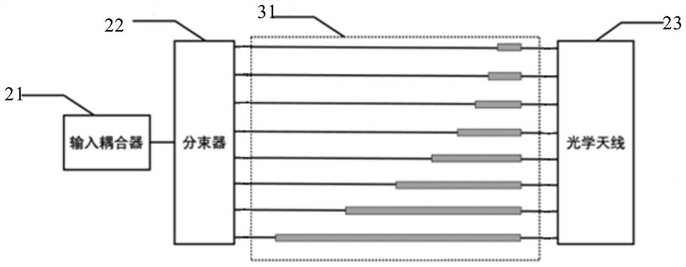
[0061] figure 1 A schematic diagram of the top view structure of the phased array laser radar provided in Embodiment 1 of the present invention, as shown in figure 1 As shown, the phased array lidar provided in this embodiment includes: an SOI substrate, an input coupler 21 , a beam splitter 22 , a phase modulator group 31 , an optical antenna 23 and a protective layer.
[0062] Wherein, the input coupler 21, the beam splitter 22, the phase modulator group 31 and the optical antenna 23, which are sequentially connected by optical paths, are formed in the SOI substrate, and the protective layer is located at the input coupler 21, the beam splitter 22, and the phase modulator group 31 And above the optical antenna 23.
[0063] Specifically, such as figure 2 As shown, the SOI substrate includes: a bottom silicon layer 11 , a buried oxide layer 12 and a top silicon layer 13 .
[0064] Wherein, the buried oxide layer 12 is located in the middle of the bottom silicon layer 11 an...
Embodiment 2
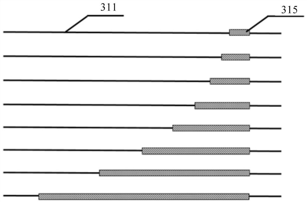
[0097] Figure 4 A schematic diagram of the structure of the phase modulator group in the phased array laser radar provided by Embodiment 2 of the present invention, FIG. Such as Figure 4 As shown, the phase modulator group in the phased array laser radar provided in this embodiment is based on the phased array laser radar provided in Embodiment 1 of the present invention, and further refines the phase modulator group, then this embodiment The provided phased array lidar also includes the following technical solutions.
[0098] Further, in this embodiment, the number of phase modulator groups is two groups.
[0099] Wherein, the heating lengths of waveguides 311 corresponding to adjacent phase modulators in the first phase modulator group 31 are in a monotonically increasing proportional relationship, and the heating lengths of waveguides 311 corresponding to adjacent phase modulators in the second phase modulator group 32 are There is a monotonically decreasing proportion...
Embodiment 3
[0113] Figure 8 A schematic flow chart of the phased array lidar scanning method provided in Embodiment 3 of the present invention, as shown in Figure 8 As shown, the phased array laser radar scanning method provided in this embodiment is a scanning method performed on the basis of the phased array laser radar provided in Embodiment 1, then the scanning method of the phased array laser radar provided in this embodiment includes The following steps:
[0114] Step 101, determine the reference voltage value corresponding to each phase modulator in the phase modulator group, and each reference voltage value forms a reference voltage list.
[0115] Wherein, the reference voltage value is a corresponding voltage value when the light spot output by the phased array laser radar reaches the global best light spot shape. When the output spot reaches the global optimal spot shape, the light intensity is the strongest and the positions of the main lobe and grating lobe are consistent ...
PUM
 Abstract
Description
Claims
Application Information
 - R&D
- Intellectual Property
- Life Sciences
- Materials
- Tech Scout
- Unparalleled Data Quality
- Higher Quality Content
- 60% Fewer Hallucinations
Browse by: Latest US Patents, China's latest patents, Technical Efficacy Thesaurus, Application Domain, Technology Topic, Popular Technical Reports.
© 2025 PatSnap. All rights reserved.Legal|Privacy policy|Modern Slavery Act Transparency Statement|Sitemap|About US| Contact US: help@patsnap.com


