Air bed layer type gravity winnowing machine
A bed-type, winnowing machine technology, applied in the direction of separating solids from solids with airflow, solid separation, filtering, etc., can solve the problems of high equipment cost, waste of wind pressure, inconsistent bulkiness, etc., and achieve reduction Small equipment size, guaranteed winnowing effect and enhanced sorting effect
- Summary
- Abstract
- Description
- Claims
- Application Information
AI Technical Summary
Problems solved by technology
Method used
Image
Examples
Embodiment 1
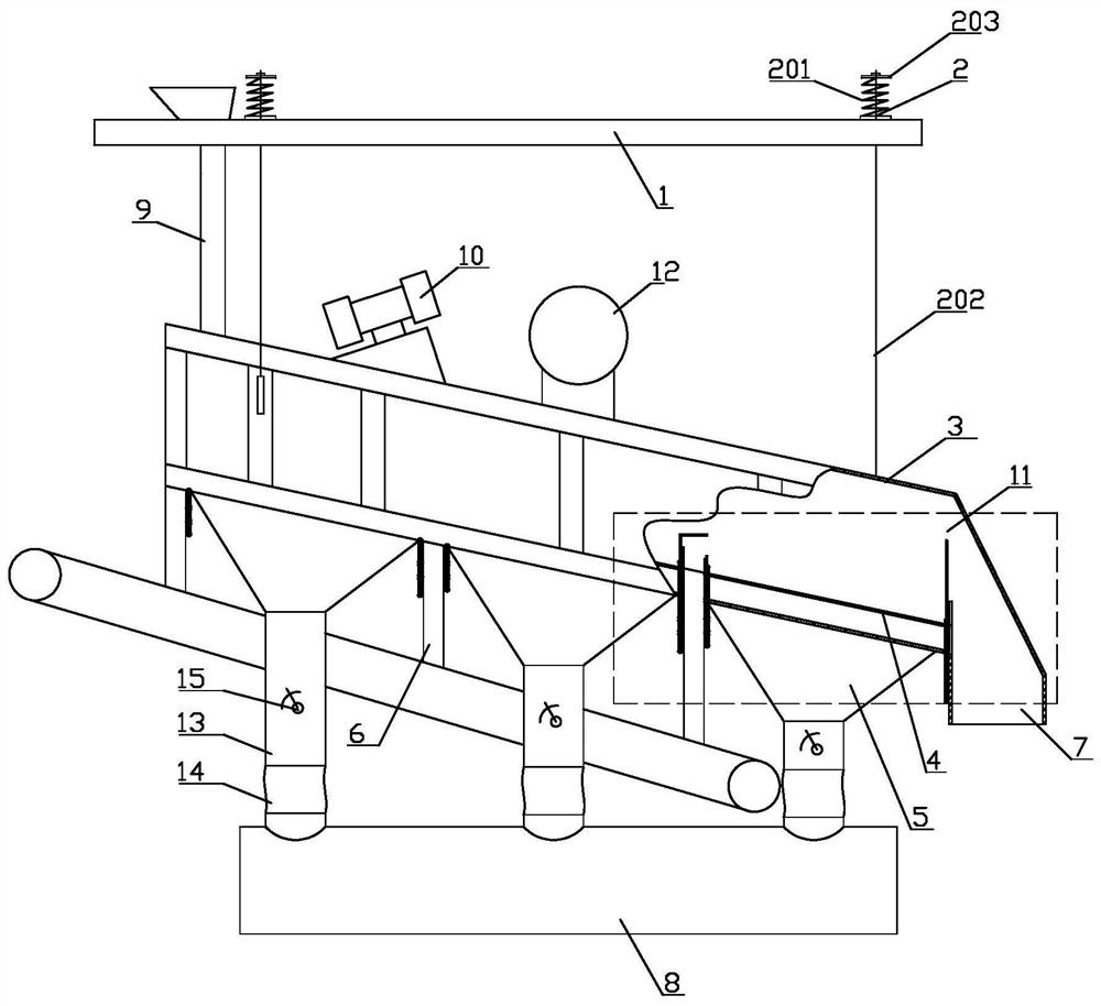
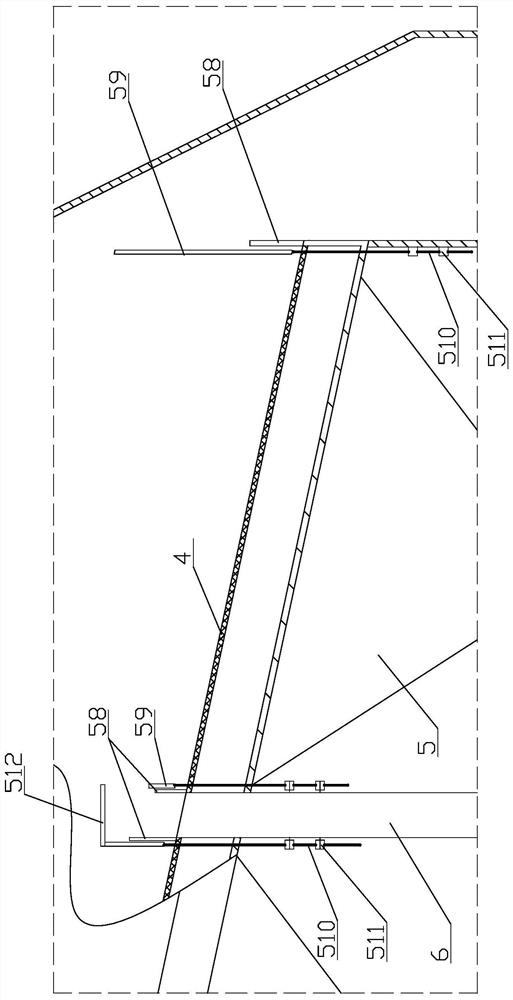
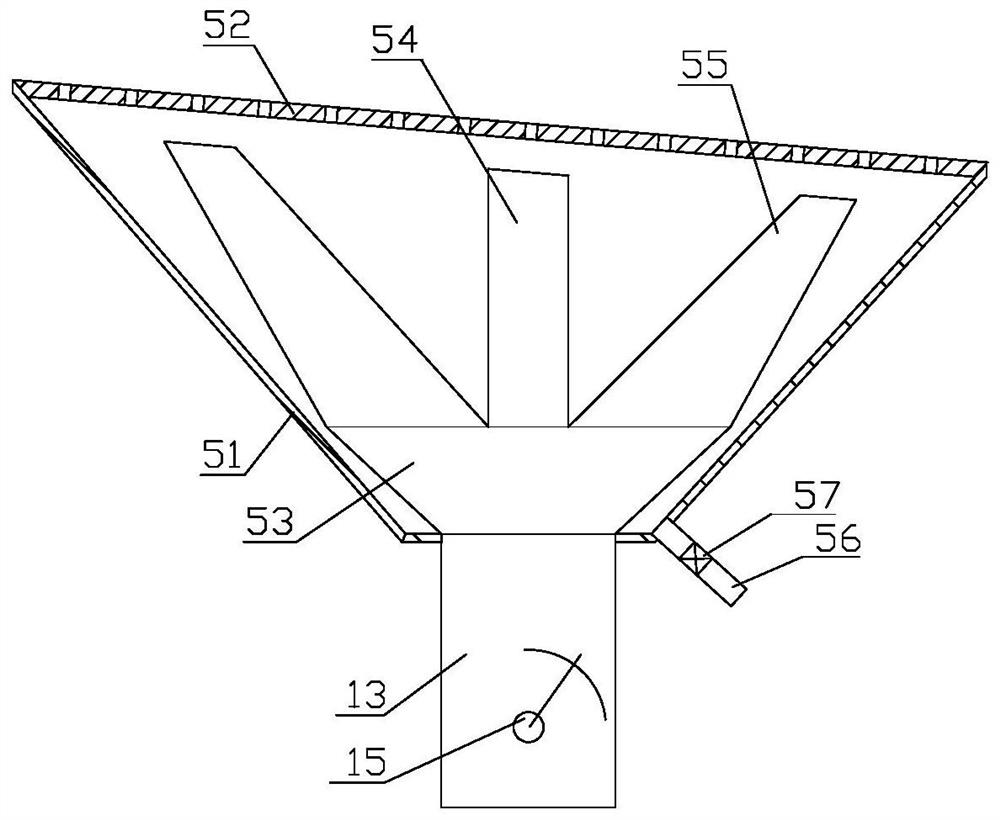
[0024] Embodiment 1: as Figure 1 to Figure 3 As shown, the air bed type gravity winnowing machine includes a frame 1, a suspension device 2, a casing 3, a screen body 4, an air chamber 5, a gangue discharge bucket 6, a clean coal discharge pipe 7 and a main air pipe 8, The casing 3 is arranged obliquely, and the casing 3 is suspended below the frame 1 through the suspension device 2. The suspension device 2 includes a spring 201 and a pull rod 202. The spring 201 is fixed on the top of the frame 1, and a pressing plate 203 is fixed on the top of the spring 201. , the top end of the pull rod 202 is fixedly connected to the pressure plate 203 through the spring 201 , and the bottom end of the pull rod 202 is movable through the frame 1 and fixedly connected to the housing 3 . The casing 3 and the sieve body 4 are suspended under the frame 1 through the pull rod 202 and the spring 201, wherein the spring 201 realizes the damping effect;
[0025]The top of the high end of the ho...
Embodiment 2
[0030] Embodiment 2: its overall structure is identical with embodiment 1, and difference is, as Figure 4 As shown, it also includes induced draft fan 16 and dust collector 17, and the air inlet of induced draft fan 16 is communicated with the air outlet pipeline of dust collector 17, and the air outlet of induced draft fan 16 is communicated with the inlet of main air duct 8, and exhaust pipe 12 It communicates with the air inlet pipeline of the dust collector 17. The gas discharged from the casing 3 enters the dust collector 17 under the suction of the induced draft fan 16 to be filtered, and the filtered coal powder can be mixed with clean coal, and the filtered gas is sent to the main air separator. In the air duct 8, it enters the air chamber 5 through the air inlet duct 13, and by increasing the induced draft fan 16 and the dust collector 17, on the one hand, the gas discharged from the exhaust duct 12 can be filtered and purified to reduce pollution; on the other hand,...
Embodiment 3
[0032] Embodiment 3: its overall structure is identical with embodiment 2, and difference is, as Figure 5 and Image 6 As shown, the dust collector 17 includes a bag filter main body 171, and the bag filter main body 171 includes structures such as a dust collector housing, a blowback mechanism, an air inlet, an air outlet, a cloth bag 175, a tube plate 179, and a discharge auger. In the example, the air inlet is set on the side of the dust removal chamber, the air outlet is set on the top of the dust collector shell above the tube plate 179, and the blowback mechanism is set inside the dust collector shell above the tube plate 179; After the tuyere enters the dust removal chamber 172, it is filtered by the cloth bag 175, and the clean air passes through the cloth bag 175 to reach the inside of the dust collector shell above the tube plate 179, gathers, and then is discharged through the air outlet;
[0033] In the dust removal chamber 172 of the main body 171 of the bag fil...
PUM
 Abstract
Description
Claims
Application Information
 - R&D
- Intellectual Property
- Life Sciences
- Materials
- Tech Scout
- Unparalleled Data Quality
- Higher Quality Content
- 60% Fewer Hallucinations
Browse by: Latest US Patents, China's latest patents, Technical Efficacy Thesaurus, Application Domain, Technology Topic, Popular Technical Reports.
© 2025 PatSnap. All rights reserved.Legal|Privacy policy|Modern Slavery Act Transparency Statement|Sitemap|About US| Contact US: help@patsnap.com


