Corner polishing machine for building

A kind of polishing machine and technology for construction, which is applied in the direction of grinding frame, grinding machine tool, machine tool suitable for grinding workpiece plane, etc. It can solve the problem of incomplete ground grinding, insufficient continuous stability, and inability to polish the corners of the building. The machine is close to the wall and other problems, so as to avoid dust flying and improve work efficiency

Inactive Publication Date: 2021-10-26
ZHEJIANG IND POLYTECHNIC COLLEGE
View PDF0 Cites 0 Cited by
  • Summary
  • Abstract
  • Description
  • Claims
  • Application Information

AI Technical Summary

Problems solved by technology

[0003] The existing corner grinder for construction is a cart style, and the outer side of the grinding sheet of the existing construction edge grinder is covered with a dust cover, which hinders the grinding sheet, causing the existing building The corner grinder cannot be used to grind close to the wall, and at the same time, it is necessary to manually apply a force close to the wall. When the wall is curved, the artificial force is often not stable enough to grind the corners of the building. The machine is close to the wall, resulting in incomplete ground grinding at the corners of the building, requiring multiple grindings, which will greatly affect the efficiency of ground grinding, and at the same time, some cement waste will be splashed on the walls at the corners of the building , so it is also necessary to grind the walls at the corners of the building

Method used


Image

  • Corner polishing machine for building
  • Corner polishing machine for building
  • Corner polishing machine for building

Examples


Embodiment Construction

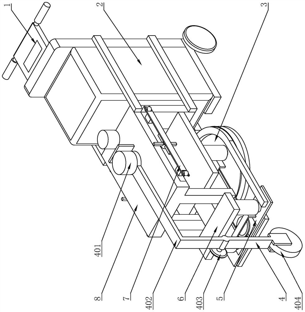
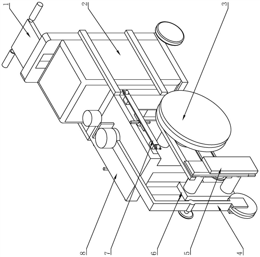
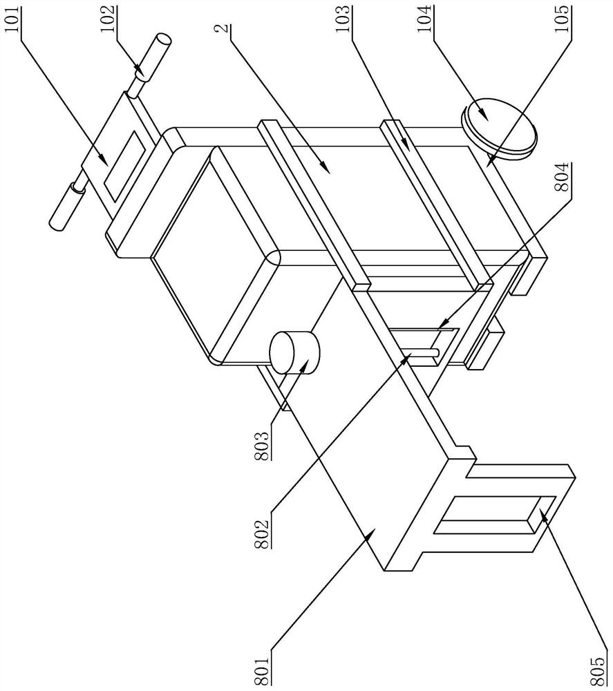
[0036] The following are specific embodiments of the present invention and in conjunction with the accompanying drawings, the technical solutions of the present invention are further described, but the present invention is not limited to these embodiments.

[0037] Such as Figure 1-Figure 6 As shown, the corner grinder used in this building includes a push mechanism 1 and an installation mechanism 8. The push mechanism 1 includes an L-shaped carrier frame 105. A battery 2 is arranged above the L-shaped carrier frame 105. The two sides of the L-shaped carrier frame 105 Both sides are fixed with two fixed rods 103, and the installation mechanism 8 includes a placement plate 801. The placement plate 801 is in an inverted U shape. Symmetrical lifting groove 805, the inside of the lifting groove 805 near the fixed rod 103 side is rotated with a second threaded rod 802, the inside of the lifting groove 805 near the fixed rod 103 side is fixed with a sliding rod 804, and the top of ...


PUM


Abstract

The invention provides a corner polishing machine for a building, and belongs to the field of building machinery. The machine solves the problem that an existing corner polishing machine cannot be used for effectively and comprehensively polishing corners of the building. The machine comprises a pushing mechanism and a mounting mechanism, the pushing mechanism comprises an L-shaped bearing frame, a storage battery is arranged above the L-shaped bearing frame, two fixing rods are fixed to each of the two sides of the L-shaped bearing frame, the mounting mechanism comprises a placing plate, the end of the placing plate is fixed between the multiple fixing rods, two lifting grooves are formed in the placing plate, an extrusion mechanism is arranged above the placing plate, rotating mechanisms are arranged in the interiors of the two lifting grooves, a grinding mechanism and a polishing mechanism are arranged below each rotating mechanism, belts are arranged between the grinding mechanisms and the polishing mechanisms, and an adjusting mechanism is arranged below the placing plate. According to the machine, the ground at wall edges and wall corners and flat wall close to the ground can be polished, and therefore building corners can be effectively and comprehensively polished.

Description

technical field [0001] The invention belongs to the technical field of construction machinery and relates to an edge grinder for construction. Background technique [0002] During the building construction process, some cement wastes such as cement, sand ash or concrete will remain on the floor of the floor. If it is not cleaned up in time, it will easily cause hollowing when decorating the floor. The corner grinder for construction is mainly used for grinding the ground beside the wall. It can effectively grind terrazzo, concrete surface, epoxy mortar layer and old epoxy floor, etc., so as to keep the inner corners of the building smooth. [0003] The existing corner grinder for construction is in the form of a cart, and the outer side of the grinding sheet of the existing construction edge grinder is covered with a dust cover, which hinders the grinding sheet, causing the existing building The corner grinder cannot be used to grind close to the wall, and at the same time,...

Claims


Application Information

Patent Timeline
Patent Type & Authority Applications(China)
IPC IPC(8): B24B37/10B24B37/11B24B37/34B24B7/18B24B41/02B24B41/04B24B47/04B24B47/12B24B55/00B24B55/06B24B55/12
CPCB24B37/10B24B37/11B24B37/34B24B7/18B24B41/02B24B41/04B24B47/04B24B47/12B24B55/00B24B55/06B24B55/12
Inventor 高昂
Owner ZHEJIANG IND POLYTECHNIC COLLEGE
Why Eureka
Try Eureka