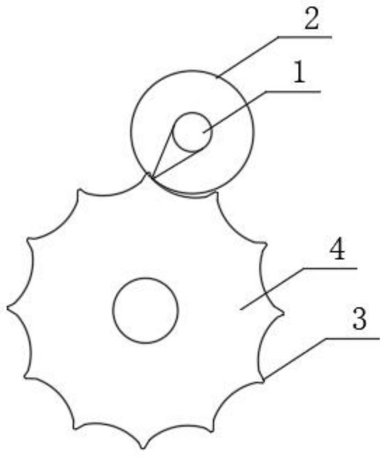
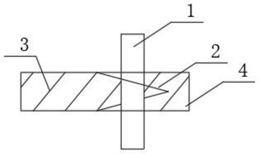
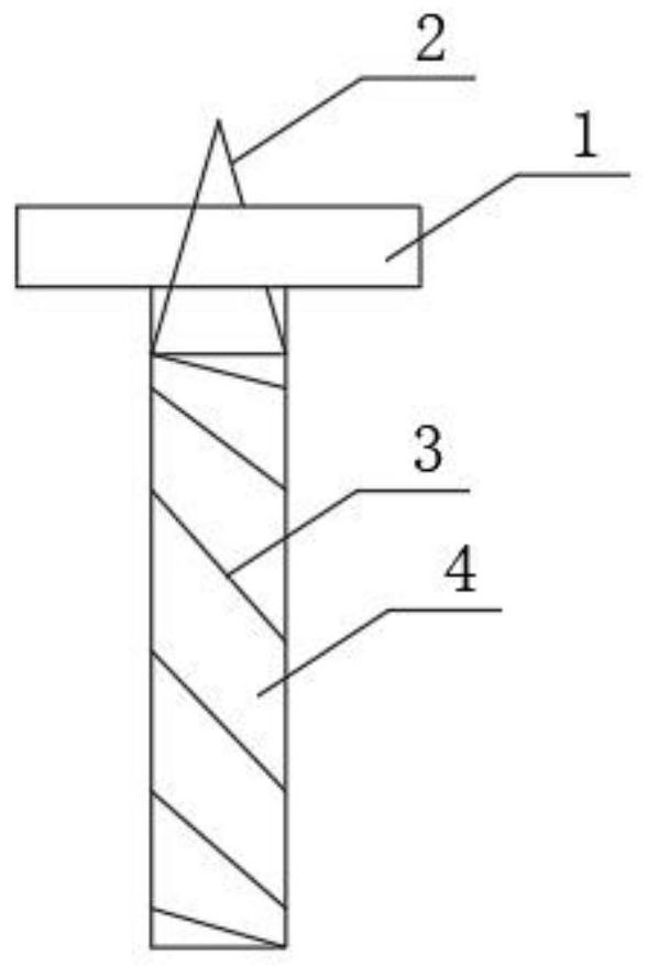
Spiral curved wheel transmission mechanism and engine with same
A technology of transmission mechanism and helical wheel, applied in the direction of gear transmission, transmission, components with teeth, etc., can solve the problems of environmental pollution, energy depletion, etc., and achieve the effect of energy security and low social comprehensive cost
- Summary
- Abstract
- Description
- Claims
- Application Information
AI Technical Summary
Problems solved by technology
Method used
Image
Examples
Embodiment 1
[0166] Use fixed objects such as heavy objects and buildings to generate static pressure on the pressure generating device to produce power generation.
[0167] Pressure generating device: jack
[0168] The installation method of the pressure generating device: the bottom of the jack is connected with the dowel rod, and the pressure-bearing travel rod is not connected with the frame to directly withstand the fixed objects such as heavy objects and buildings. After the pressure rod is retracted, the weight of fixed objects such as heavy objects and buildings will not fall on the frame, that is, the pressure rod will be stressed when it is lifted, and the jack and the frame will not be stressed when retracted.
[0169] Pressure control mode: manual, mechanical, electric drive servo motor or stepper motor control.
[0170] This embodiment provides power generation for the non-moving generator, does not consume natural resources, and can save energy costs. This embodiment can al...
Embodiment 2
[0172] Take the working mode-helical crank wheel engine as an example.
[0173] The pressure generating device adopts a jack, and the pressure control method adopts an electric drive servo motor or a stepping motor, and is controlled by a low-speed heavy-duty motor.
[0174] A. Convert the weight of the train carriage and the weight of the goods into driving power.
[0175] Installation method: see Figure 29-Figure 31, in the figure: 16, bogie; 17, central axis of bogie; 18, train wheel; 19, train axle; 20, train carriage; 21, additional U-shaped pressure steel sheet; 22, additional power transmission device ; 23. The additional power transmission bracket.
[0176] B. Convert the weight of the truck compartment and the weight of the cargo into driving power.
[0177] Installation method: see Figure 32 and Figure 33 , in the figure: 24, truck compartment; 25, airbag suspension; 26, shock absorber; 27, bracket; 28, guide arm assembly; 29, axle; 30, automobile wheel; Ste...
Embodiment 3
[0182] The pressure generating device adopts jack series, hydraulic booster series, booster cylinder series, booster pump series, pressure test pump or pneumatic hydraulic pump series, etc. The pressure control method adopts electric drive servo motor or stepping motor, low speed and heavy load motor control.
[0183] Elevation diagram of the connection between the helical crank wheel engine and the differential:
[0184] Take the working mode-helical crank wheel engine as an example. See the installation diagram Figure 34 .
[0185] Take working mode two helical crank engine as an example. See the installation diagram Figure 35 .
[0186] Take the working mode five helical crank wheel engine as an example. See the installation diagram Figure 36
[0187] Take the working mode six helical crank wheel engine as an example. See the installation diagram Figure 37 .
[0188] Take working mode eight helical crank wheel engine as example. See the installation diagram ...
PUM
 Abstract
Description
Claims
Application Information
 - R&D
- Intellectual Property
- Life Sciences
- Materials
- Tech Scout
- Unparalleled Data Quality
- Higher Quality Content
- 60% Fewer Hallucinations
Browse by: Latest US Patents, China's latest patents, Technical Efficacy Thesaurus, Application Domain, Technology Topic, Popular Technical Reports.
© 2025 PatSnap. All rights reserved.Legal|Privacy policy|Modern Slavery Act Transparency Statement|Sitemap|About US| Contact US: help@patsnap.com


