Building indoor decorative plate machining production line

A technology for interior decorative panels and production lines, applied in metal processing equipment, manufacturing tools, grinding workpiece supports, etc., can solve the problems of low wire drawing accuracy, difficulty in affecting the wire drawing accuracy by the body of the wire drawing abrasive belt, and wire drawing processing of the curtain wall aluminum veneer. Achieve the effect of improving the quality of wire drawing, solving the low efficiency of wire drawing, and broadening the scope of application

Active Publication Date: 2021-10-29
南通欧本建筑科技有限公司
View PDF6 Cites 2 Cited by
  • Summary
  • Abstract
  • Description
  • Claims
  • Application Information

AI Technical Summary

Problems solved by technology

[0008] The purpose of the present invention is to address the deficiencies of the prior art and provide a production line for processing interior decorative panels. Through the use of the main wire drawing assembly, the clamping assembly, the auxiliary wire drawing assembly, and the dust removal assembly, the surface and both sides of the aluminum curtain wall The wire drawing process solves the problems that the existing curtain wall wire drawing machine has low drawing accuracy, it is difficult to clean the wire drawing abrasive belt body, which easily affects the subsequent drawing accuracy, and it is difficult to draw the curtain wall aluminum veneer of a specific shape after assembly.

Method used


Image

  • Building indoor decorative plate machining production line
  • Building indoor decorative plate machining production line
  • Building indoor decorative plate machining production line

Examples


Embodiment 1

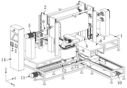
[0049] Such as Figure 7 As shown, a production line for processing interior decorative boards for buildings includes: a workbench 1; the workbench 1 includes a main support frame 101, and the side supports 102 are connected to both sides of the main support frame 101 along the X-axis direction, and the side support platforms 102 are The surface is respectively connected with the first support column 103, the second support column 104 and the third support column 105, and the side support frame 106 is connected to one side of the main support frame 101 along the X-axis direction;

[0050] It should be noted that the second support column 104 is located in the middle of the upper surface of the side support platform 102, the two groups of first support columns 103 are respectively located on both sides of the second support column 104 along the Y-axis direction, and the third support columns 105 are respectively located on the second side. A supporting column 103 is positioned ...

Embodiment 2

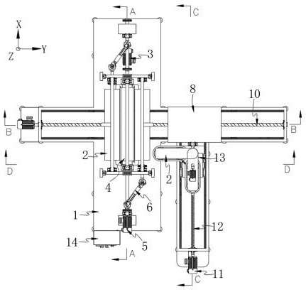
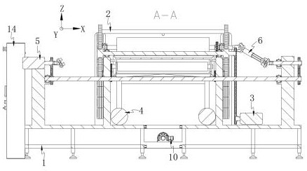
[0058] Such as Figure 1-4 As shown, the components that are the same as or corresponding to those in the first embodiment are marked with the corresponding reference numerals in the first embodiment. For the sake of simplicity, only the differences from the first embodiment will be described below. The difference between this embodiment two and embodiment one is:

[0059] A production line for building interior decoration panels, which also includes a main body drawing assembly 2, which is slidably connected to the top of a side support platform 102 for drawing the upper surface of an aluminum curtain wall 8; the first driving part 3 is used for driving the adjacent The two main body wire drawing assemblies 2 reciprocate along the Z-axis direction; there are two main body wire drawing assemblies 2, and the inner surfaces of the two main body wire drawing assemblies 2 are connected by transmission through the first driving part 3;

[0060]It should be noted that the two main ...

Embodiment 3

[0070] Such as figure 1 , 2 , 4, and 6, wherein the same or corresponding components as those in Embodiment 1 use the corresponding reference numerals as in Embodiment 1. For the sake of brevity, only the differences from Embodiment 1 will be described below. The difference between this embodiment two and embodiment one is:

[0071] A production line for processing interior decorative panels for buildings, which also includes a dust removal assembly 4 connected to the top of the workbench 1, and the dust removal assembly 4 is used to remove dust from the drawing assembly 2 of the main body; it should be noted that most of the existing dust removal devices only It can clean up the scrap attached to the surface of the aluminum curtain wall 8, but the scrap attached to the abrasive belt is difficult to clean, causing the scrap attached to the wire drawing belt to cause secondary damage to the aluminum curtain wall 8, and at the same time, the scrap attached to the wire drawing b...


PUM


Abstract

The invention discloses a building indoor decorative plate machining production line, and belongs to the technical field of aluminum plate curtain wall production equipment. The building indoor decorative plate machining production line comprises a workbench, a clamping assembly, a main wire drawing assembly, a first driving part, a dust removal assembly and an auxiliary wire drawing assembly. The clamping assembly is slidably connected to the top of a main supporting frame and used for positioning and clamping a curtain wall aluminum plate. The main wire drawing assembly is connected to the top of a side supporting table in a sliding manner. The dust removal assembly is used for carrying out dust removal treatment on the main wire drawing assembly. The auxiliary wire drawing assembly is connected to the top of the side supporting frame in a sliding manner and used for conducting wire drawing treatment on the two side faces, in the X-axis direction, of the curtain wall aluminum plate. Through use of the main wire drawing assembly, the clamping assembly, the auxiliary wire drawing assembly and the dust removal assembly, the problems that an existing curtain wall wire drawing machine is low in wire drawing precision, a wire drawing abrasive belt is difficult to clean, and wire drawing treatment to an assembled curtain wall aluminum veneer is difficult are solved.

Description

technical field [0001] The invention relates to the technical field of aluminum curtain wall production equipment, in particular to a production line for processing interior decorative panels for buildings. Background technique [0002] The curtain wall is the outer wall enclosure of the building. It is not load-bearing and hangs up like a curtain, so it is also called "curtain wall". It is a light-weight wall with decorative effect commonly used in modern large-scale and high-rise buildings. Composed of panels and supporting structure systems, it can have a certain displacement capacity relative to the main structure or itself has a certain deformation capacity, and does not bear the role of the main structure. The building envelope structure or decorative structure, the curtain wall can be divided into: architectural Curtain wall, component building curtain wall, unitized curtain wall, glass curtain wall, stone curtain wall, metal plate curtain wall, full glass curtain wal...

Claims


Application Information

Patent Timeline
Patent Type & Authority Applications(China)
IPC IPC(8): B24B21/00B24B41/06B24B55/08B24B41/00B24B49/00B24B27/02
CPCB24B21/006B24B21/008B24B41/06B24B55/08B24B41/007B24B49/00B24B27/02
Inventor 陈明
Owner 南通欧本建筑科技有限公司
Why Eureka
Try Eureka