

Annealing equipment for invisible protective mesh wire rope processing
A technology for annealing equipment and wire ropes, applied in the field of heat treatment, can solve problems such as uneven heating of wire ropes, and achieve the effects of large dust removal range, uniform heating, and improved adaptability
- Summary
- Abstract
- Description
- Claims
- Application Information
AI Technical Summary
Problems solved by technology
Method used
Image

Examples
Embodiment 1
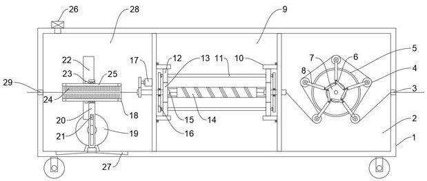
[0035] Embodiments of the present invention provide annealing equipment for processing invisible protective mesh wire ropes, such as Figure 1-2 shown, including:
[0036] Box 1. In this embodiment, self-locking rollers are preferably installed at the bottom of the box 1 evenly and symmetrically to facilitate the movement of the equipment. The box 1 is provided with adjacent annealing chambers 9 and cooling chambers 2, preferably Different chambers are separated by partitions. The two side walls of the box body 1 are respectively provided with an inlet 29 and an outlet 3. The sizes of the inlet 29 and the outlet 3 are designed according to the needs and are not limited. During operation, the steel wire rope is passed through the inlet 29. , passes through the annealing chamber 9 and the cooling chamber 2, and passes through the outlet 3. Further, a box door is installed on the box body 1 to facilitate the installation of the wire rope;
[0037] The annealing unit, which is in...
Embodiment 2
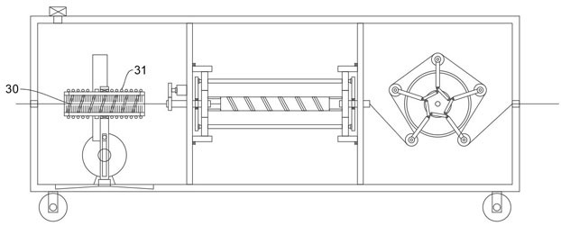
[0044] This embodiment is based on Embodiment 1, such as image 3 As shown, in order to preheat the steel wire rope, the outer wall of the dust removal sleeve 18 is wound with a plurality of circles of electric heating wires 31. Further, the inner wall of the dust removal sleeve 18 is provided with a spiral guide bar 30, and the spiral guide bar 30 is provided when the dust removal sleeve 18 rotates. Rotation can lead the dust out of the dust removal sleeve 18, and at the same time, a certain cyclone is formed to help the dust discharge.
Embodiment 3
[0046] This embodiment is based on Embodiment 2, such as Figure 4-5 As shown, further, a plurality of elastic protrusions 32 are provided at intervals on one side of the groove wall of the movable groove, and the outer wall of the pin shaft 21 is also provided with a plurality of elastic protrusions 32 in the circumferential direction. The elastic protrusions 32 are preferably rubber. The material can be adhered by glue, the elastic protrusions 32 on the pin shaft 21 and the elastic protrusions 32 on the groove wall of the movable groove can interfere and cooperate, and when the pin shaft 21 moves in the movable groove, the elastic protrusions 32 intermittently interfere and cooperate to make the mounting plate 20 Vibration is generated, so that the dust removal sleeve 18 vibrates, which further helps to discharge the dust in the dust removal sleeve 18 and prevents the dust from falling back onto the wire rope again.
PUM
 Abstract
Description
Claims
Application Information