Timing measurement device for soil erosion amount

A technology of soil erosion and timing measurement, which is applied to measuring devices, material analysis through optical means, instruments, etc., can solve the problems of large accuracy error of soil erosion, limited number of "steel drills", and large error of h value, etc. Achieve the effect of accurate water and soil loss, reduce the frequency of manual on-site measurement, and not easy to lose

Active Publication Date: 2021-10-29
安徽省(水利部淮河水利委员会)水利科学研究院(安徽省水利工程质量检测中心站)
View PDF4 Cites 2 Cited by
  • Summary
  • Abstract
  • Description
  • Claims
  • Application Information

AI Technical Summary

Problems solved by technology

[0005] For the measurement of soil erosion by the above-mentioned "steel drill method", the obtained Qd mainly depends on β, H, S, and needs There are many variables to be measured; moreover, it is necessary to manually measure the corresponding β, H, and S for each measuring nail, and the operation is cumbersome; in addition, due to the limitation of the slope, the number of "steel drills" inserted is limited, and 80m2, and the slope angles corresponding to different areas of the entire slope may be different, that is, there may be a certain gap in the size of β at different positions , and the calculated h=H·cosβ, β will also affect the accuracy of h to a certain extent; and the current measurement method is to ignore the influence of this value
Therefore, the sample size is small (the number of steel drills), the error of the calculated h value is large, and the accuracy error of the final measured water and soil loss is large
[0006] For the existing "brazing method", if you want to reduce the measurement error, the most feasible operation in theory is to ensure that each measurement, " The length direction of the "steel brazing" is always perpendicular to the slope, but this operation is obviously unrealistic, because the slope often has unevenness

Method used


Image

  • Timing measurement device for soil erosion amount
  • Timing measurement device for soil erosion amount
  • Timing measurement device for soil erosion amount

Examples


Embodiment 1

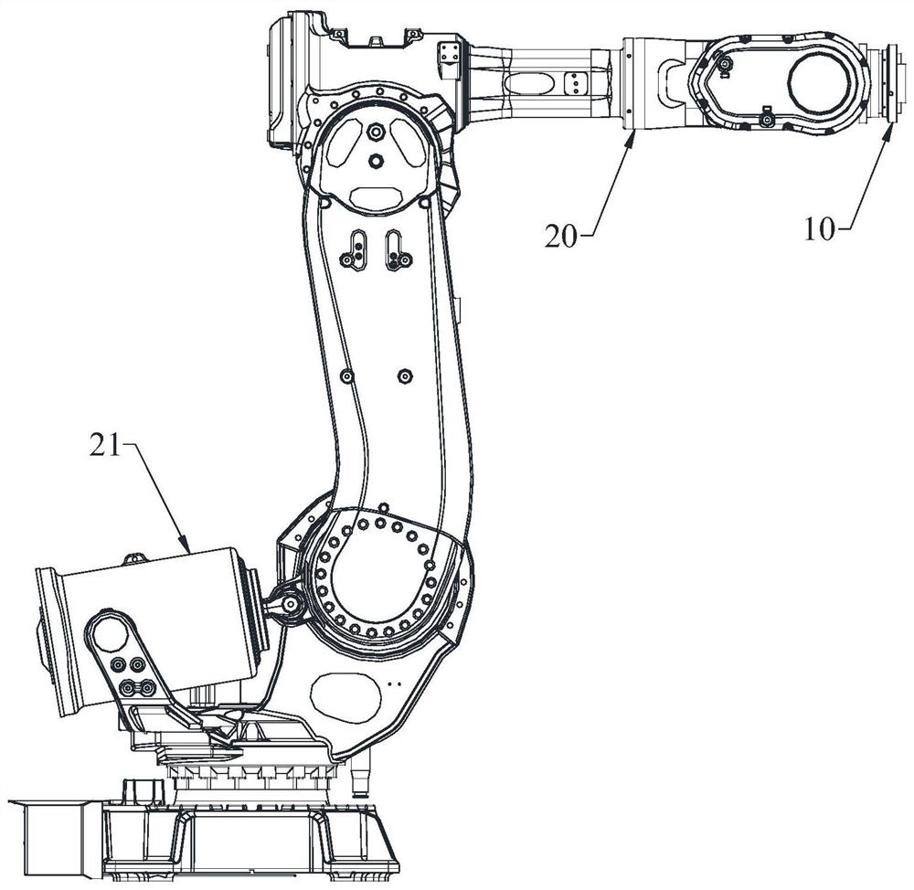
[0049] Such as figure 2 As shown, the soil erosion timing measurement device includes:

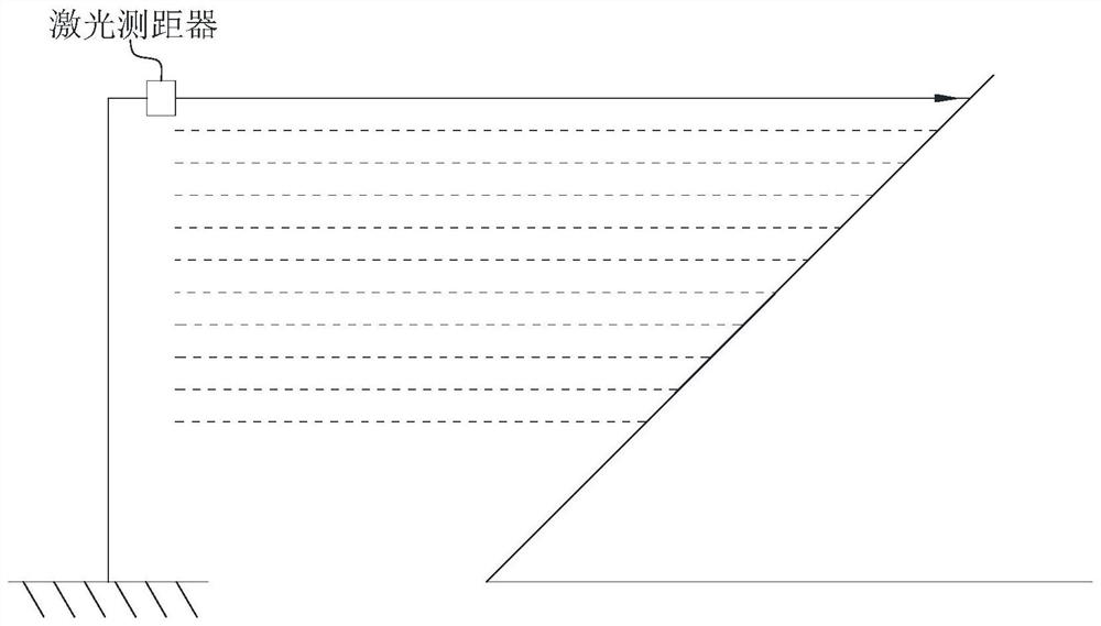
[0050] A laser rangefinder 10 is used to measure the distance between it and the slope to obtain a distance measurement value;

[0051] Measuring robot 20, the laser range finder 10 is fixedly installed on the mobile end of the measuring robot 20, and the measuring robot 20 controls the laser range finder 10 to scan the slope according to the specified track and frequency and collect the distance measurement value;

[0052] Timing control module, used to control the time interval between two adjacent rounds of measurement;

[0053] Data temporary storage module, used for temporary storage of data;

[0054] The data remote transmission module is used to send the temporary storage data to the control terminal;

[0055] Control the terminal to perform operations on the sent data.

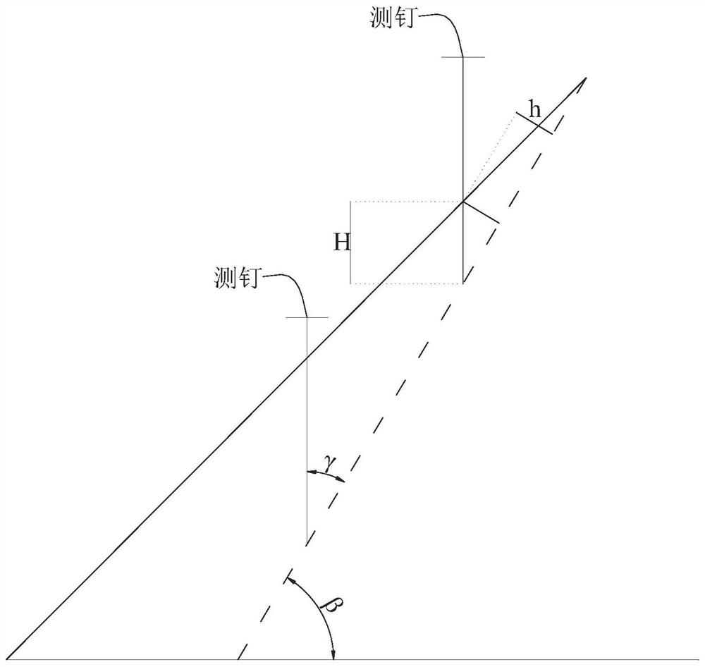
[0056] The measurement principle of the soil erosion timing measurement device is as follows:

[0057] The...

Embodiment 2

[0067] In this embodiment, the specified trajectory in the first round / second round of scanning process described in Embodiment 1 is a "己"-like structure, such as Figure 5 shown. During each round of scanning, adjacent measurement points are set at equal intervals. In this embodiment, during each round of scanning, the density of measurement points is 300 / square meter.

Embodiment 3

[0069] In this embodiment, the specified trajectory in the first round / second round of scanning described in Embodiment 1 is a concentric circular structure, such as Figure 6 shown. During each round of scanning, adjacent measurement points are set at equal intervals.

[0070] In this embodiment, during each round of scanning, the density of measurement points is 300 / square meter.


PUM


Abstract

The invention relates to a timing measuring device for soil erosion amount. The timing measuring device comprises a laser range finder, a measuring robot, a timing control module, a data temporary storage module, a data remote transmission module and a control terminal. The measuring robot controls the laser range finder to perform first-round scanning on the slope surface according to a specified track and a specified frequency, and a first-round distance measurement value is acquired; the timing control module is used for controlling the time interval of second-round scanning, the measuring robot controls the laser range finder to conduct second-round scanning on the slope surface according to the specified track and the specified frequency, and a second-round distance measurement value is obtained through collection; and the first-round spacing measurement value and the second-round spacing measurement value are sent to the control terminal through the data remote transmission module, and calculation at the control terminal is performed to obtain the soil erosion amount of the slope. Sensors or measuring nails do not need to be arranged on the slope surface, loss is not prone to occurring, the density of measuring points is larger, and experiment and measuring results can be better guaranteed.

Description

technical field [0001] The invention relates to a soil erosion timing measurement device, which belongs to the technical field of water and soil conservation monitoring. Background technique [0002] The traditional soil erosion is measured by the "steel drill method". The most important monitoring index in the monitoring of water and soil conservation in development and construction projects is the monitoring of soil erosion. It is a method of manually bringing the required monitoring instruments to the monitoring point, each instrument works independently, and the monitoring results are recorded. . This method requires surveyors to arrive at the site regularly for monitoring. At the same time, a large number of instruments and equipment need to be carried each time. Moreover, there are large errors and many uncertain factors in manual measurement and recording, which seriously affect the accuracy of monitoring. [0003] The existing "steel drill method" to measure soil e...

Claims


Application Information

Patent Timeline
Patent Type & Authority Applications(China)
IPC IPC(8): G01N21/01G01N21/84
CPCG01N21/01G01N21/84
Inventor 朱昊宇夏小林姬钰汪邦稳张世杰张靖雨刘旦旦张卫赵黎明龙昶宇王浩宇彭栋
Owner 安徽省(水利部淮河水利委员会)水利科学研究院(安徽省水利工程质量检测中心站)
Why Eureka
Try Eureka