Illumination system for improving collimation efficiency based on Fresnel lens

A Fresnel lens and lighting system technology, applied in the direction of lenses, condensers, instruments, etc., can solve the problems of poor light collimation effect, low light efficiency, and large space occupation, so as to improve light utilization and light efficiency The effect of improving and saving costs

Active Publication Date: 2021-10-29
UNIV OF ELECTRONICS SCI & TECH OF CHINA
View PDF7 Cites 5 Cited by
  • Summary
  • Abstract
  • Description
  • Claims
  • Application Information

AI Technical Summary

Problems solved by technology

[0004] The purpose of the present invention is to overcome the problems of poor light collimation effect, low light efficiency and relatively large space occupation in the lighting system in the traditional DLP technology

Method used


Image

  • Illumination system for improving collimation efficiency based on Fresnel lens
  • Illumination system for improving collimation efficiency based on Fresnel lens
  • Illumination system for improving collimation efficiency based on Fresnel lens

Examples


Embodiment 1

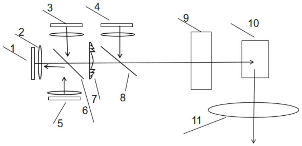
[0033] Such as image 3 As shown, the first light source 1, the third light source 3, and the fourth light source 4 radiate light of different wavelengths G, B, and R respectively. After the dichroic mirror DMB6 is reflected by the first dichroic mirror DMB6, the light is irradiated onto the light source 1 to excite the phosphor powder therein to generate more green light and increase the brightness of the green light.

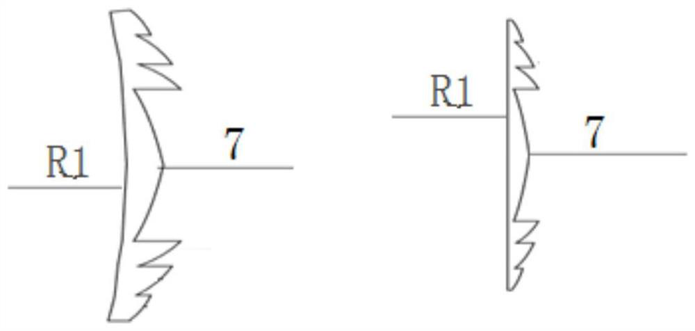
[0034] The first dichroic mirror DMB6 reflects blue light and transmits red and green light, and its transmittance curve is as follows Figure 5 and Figure 7 . The converged light beam passes through the Fresnel lens 7, and the side of the Fresnel lens 7 close to the first dichroic mirror DMB6 is a plane. After collimation, it passes through the second dichroic mirror DMR8, which reflects red light and transmits blue-green light. The transmittance curve is as follows: Figure 6 and Figure 8 . The beam passes through the array integrator, that is, the c...

Embodiment 2

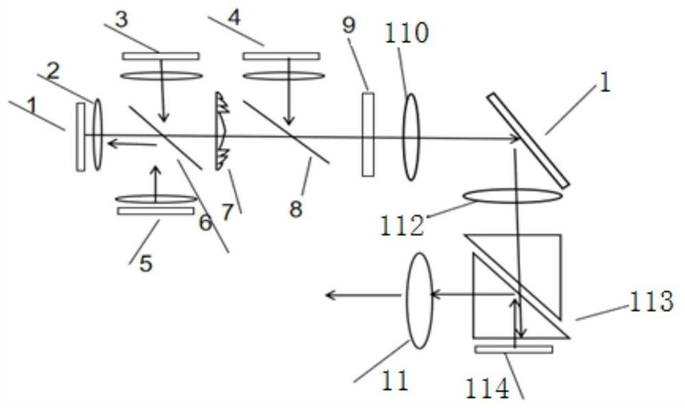
[0038] Such as Figure 4 As shown, four light sources, the fourth light source (4), the first light source (1), the third light source (3) and the fifth light source 5 respectively emit corresponding red, green, blue, blue, and the light rays pass through the converging points before the respective light sources. The lens 2 , in which the first dichroic mirror DMB6 passes the green light emitted by the first light source 1 , but reflects the blue light emitted by the third light source 3 . At the same time, the blue light emitted by the fifth light source 5 is reflected to the fluorescent powder on the green light source (1), the fluorescent powder excites the green light, and the green light can pass through the dichroic mirror DMB6. Finally, the blue light and the green light pass through the Fresnel lens 7 and are corrected. The side of the Fresnel collimator lens 7 close to the first dichroic mirror DMB6 is a concave anamorphic aspheric surface, which is close to the secon...

Embodiment 3

[0043] In the above scheme, the diameter of the Fresnel collimating lens is 20-22mm, and the thickness is 3.6mm;

[0044] In the above scheme, the right side of the Fresnel collimating lens is a convex anamorphic aspheric surface, its X meridian quadric surface coefficient is 1.04, and its radius is 23-25 ​​mm; the Y meridian quadric surface coefficient is 7.12, and its radius is 33 mm. -36mm;

[0045] In the above scheme, the left side of the Fresnel collimator lens is a concave polynomial aspheric surface with a radius of 30-35mm, a 4th-order aspheric coefficient of -4.173e-5, a 6th-order aspheric coefficient of 1.251e-7, 8th-order aspheric coefficient -1.628e-9, 10th-order aspheric coefficient 5.289e-12;

[0046] In the above solution, the material of the Fresnel collimating lens can be 350R, the refractive index of 620nm wavelength is 1.507631, the refractive index of 550nm wavelength is 1.510968, and the refractive index of 460nm wavelength is 1.517871;

[0047] In the ...


PUM


Abstract

The present invention discloses an illumination system for improving the collimation efficiency based on a Fresnel lens. The illumination system comprises light sources with different wavelengths, each light source is provided with a convergent lens, and the light rays emitted by a first light source, a fifth light source and a third light source pass through the convergent lenses and first dichroscopes respectively, and then the light rays at different angles are collimated through the Fresnel collimating lens; the collimated light rays pass through a second dichroscope , the light rays emitted by the fourth light source pass through the convergent lens and then pass through the second dichroscope, the second dichroscope enables the two kinds of light rays to form a light beam and converges the light beam into a dodging system, and the light beam sequentially passes through the dodging system, a light valve system and a projection system and is finally projected on a screen.

Description

technical field [0001] The invention belongs to the technical field of projectors, and relates to an illumination system for improving collimation efficiency based on a Fresnel lens. Background technique [0002] Modern projection technology According to projection, DLP projection technology is a projection technology that is widely used at present. The DLP-based projection system can be divided into two parts: lighting and imaging. The lighting part acts as an optical engine, that is, to collimate and evenly light the light emitted by the light source, so that the light incident on the light valve system is evenly distributed in a rectangular shape. , the light valve system can better modulate the image. The most important purpose in the lighting system is to improve the light efficiency and shape the light spot. There are two important components in the illumination system, one is the collimating lens and the other is the integrator. [0003] Aspherical lenses are commo...

Claims


Application Information

Patent Timeline
Patent Type & Authority Applications(China)
IPC IPC(8): G03B21/20G02B3/08G02B19/00
CPCG03B21/2013G03B21/2033G02B3/08G02B19/0004G02B19/0047G03B21/208
Inventor 钟建刘杰权志豪成桂霖张帅
Owner UNIV OF ELECTRONICS SCI & TECH OF CHINA
Why Eureka
Try Eureka