Glass cutting device for high-end equipment manufacturing
A glass cutting and equipment technology, applied in glass cutting devices, manufacturing tools, glass manufacturing equipment, etc., can solve the problems of inaccurate glass cutting, easy deviation of glass knives, etc., to ensure integrity, avoid manual movement of connecting rods, The effect of improving work efficiency
- Summary
- Abstract
- Description
- Claims
- Application Information
AI Technical Summary
Problems solved by technology
Method used
Image
Examples
Embodiment 1
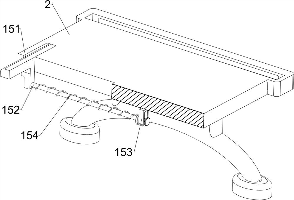
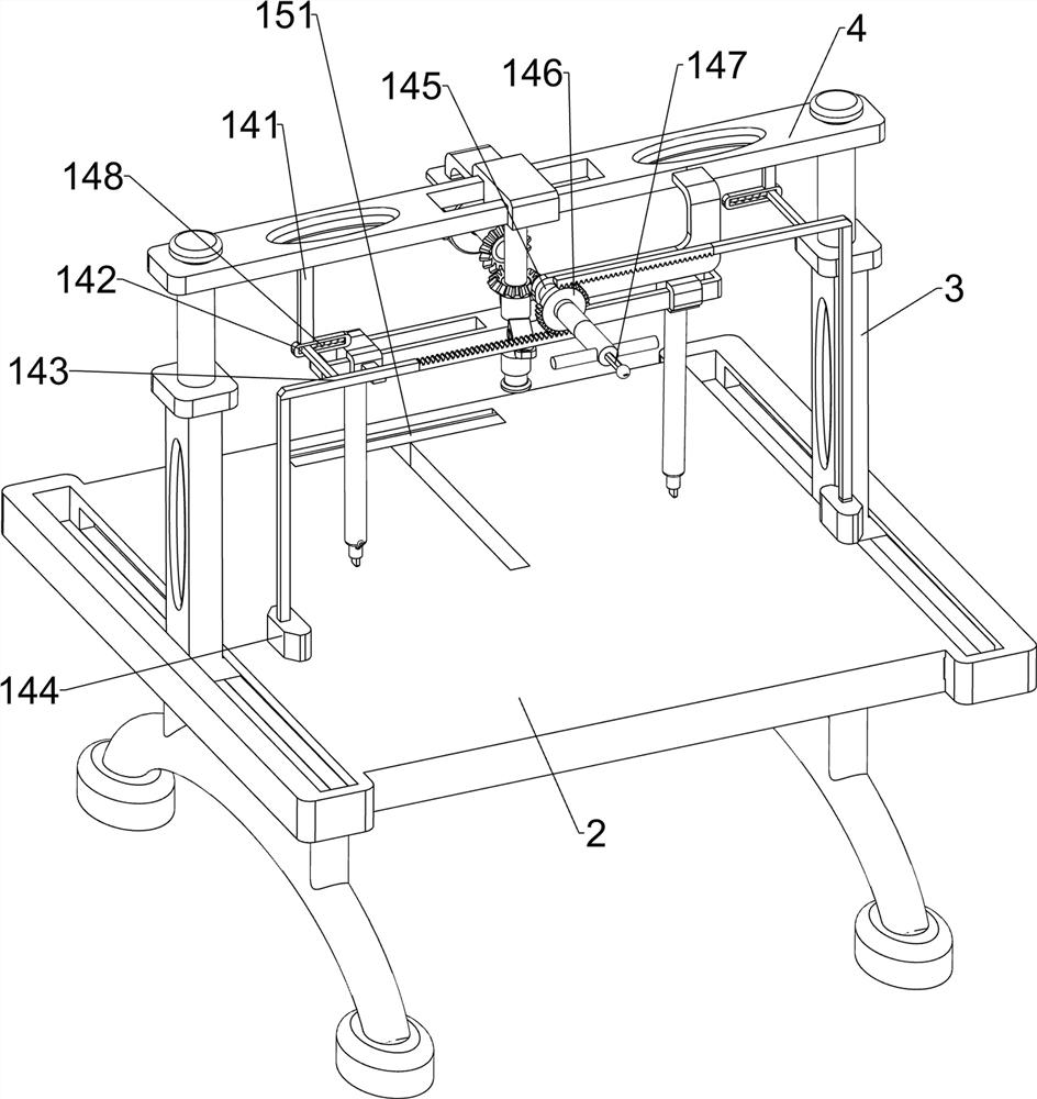
[0030] A glass cutting device for high-end equipment manufacturing, such as Figure 1-2 As shown, it includes a support leg 1, a bottom plate 2, a moving frame 3, a connecting plate 4, a guide block 5, a guide plate 6, a connecting rod 7, a nut 8, a glass cutter 9, a driving mechanism 10 and a telescopic mechanism 11, and the supporting leg 1 The top end of the base plate 2 is connected with a base plate 2, and the top of the base plate 2 is slidably connected with a mobile frame 3, and the mobile frame 3 is slidably connected with a connecting plate 4, and the middle part of the connecting plate 4 is slidably connected with a guide block 5, and the guide block The bottom of 5 is slidably connected with a guide plate 6, the left and right sides of the guide plate 6 are slidably connected with connecting rods 7, the bottoms of the left and right connecting rods 7 are connected with nuts 8, and the bottom ends of the connecting rods 7 are slidably connected. A glass knife 9 is c...
Embodiment 2
[0035] On the basis of Example 1, such as image 3 As shown, a decompression assembly 12 is also included. The decompression assembly 12 includes a sliding sleeve 121, a first guide rod 122, a decompression pad 123, a first spring 124 and a second spring 125. Sleeve 121, the first guide rod 122 is slidably connected to the front and rear sides of the sliding sleeve 121, the bottom end of the first guide rod 122 is connected to a decompression pad 123, and a first decompression pad 123 is connected to the sliding sleeve 121. The spring 124 , the first spring 124 is sleeved on the first guide rod 122 , the second spring 125 is connected between the moving frame 3 and the connecting plate 4 , and the second spring 125 is sleeved on the moving frame 3 .
[0036]The connecting plate 4 moves downward, the second spring 125 is compressed, the guide block 5 drives the sliding sleeve 121 to move downward, the first guide rod 122 drives the decompression pad 123 to move downward, the fi...
Embodiment 3
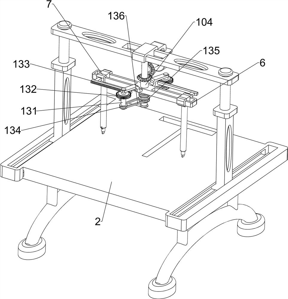
[0038] On the basis of Example 2, such as Figure 4-6 Shown, also include moving mechanism 13, and moving mechanism 13 includes the 3rd axle rod 131, one-way gear 132, short rack 133, first pulley 134, second pulley 135 flat belt 136, the middle part of guide plate 6 front and rear Both sides are rotationally connected with a third shaft 131, the top of the third shaft 131 is connected with a one-way gear 132, and the connecting rods 7 on the left and right sides are connected with a short rack 133, and the short rack 133 is connected with the one-way gear. 132, the bottom end of the third shaft 131 is connected with the first pulley 134, the bottom of the second shaft 104 is connected with the second pulley 135, and the flat belt 136 is connected between the second pulley 135 and the first pulley 134.
[0039] The starter motor 101 reverses, the second shaft 104 rotates, the first pulley 134 rotates thereupon, the flat belt 136 and the second pulley 135 rotate accordingly to ...
PUM
 Abstract
Description
Claims
Application Information
 - R&D
- Intellectual Property
- Life Sciences
- Materials
- Tech Scout
- Unparalleled Data Quality
- Higher Quality Content
- 60% Fewer Hallucinations
Browse by: Latest US Patents, China's latest patents, Technical Efficacy Thesaurus, Application Domain, Technology Topic, Popular Technical Reports.
© 2025 PatSnap. All rights reserved.Legal|Privacy policy|Modern Slavery Act Transparency Statement|Sitemap|About US| Contact US: help@patsnap.com


