A Polarization-Maintaining Dispersion Compensation Microstructure Optical Fiber
A microstructure optical fiber, color cast technology, applied in the field of optical fiber communication, can solve the problem of unmentioned inner and outer core mode coupling, and achieve the effect of good polarization-maintaining characteristics and high birefringence value
- Summary
- Abstract
- Description
- Claims
- Application Information
AI Technical Summary
Problems solved by technology
Method used
Image
Examples
Embodiment 1
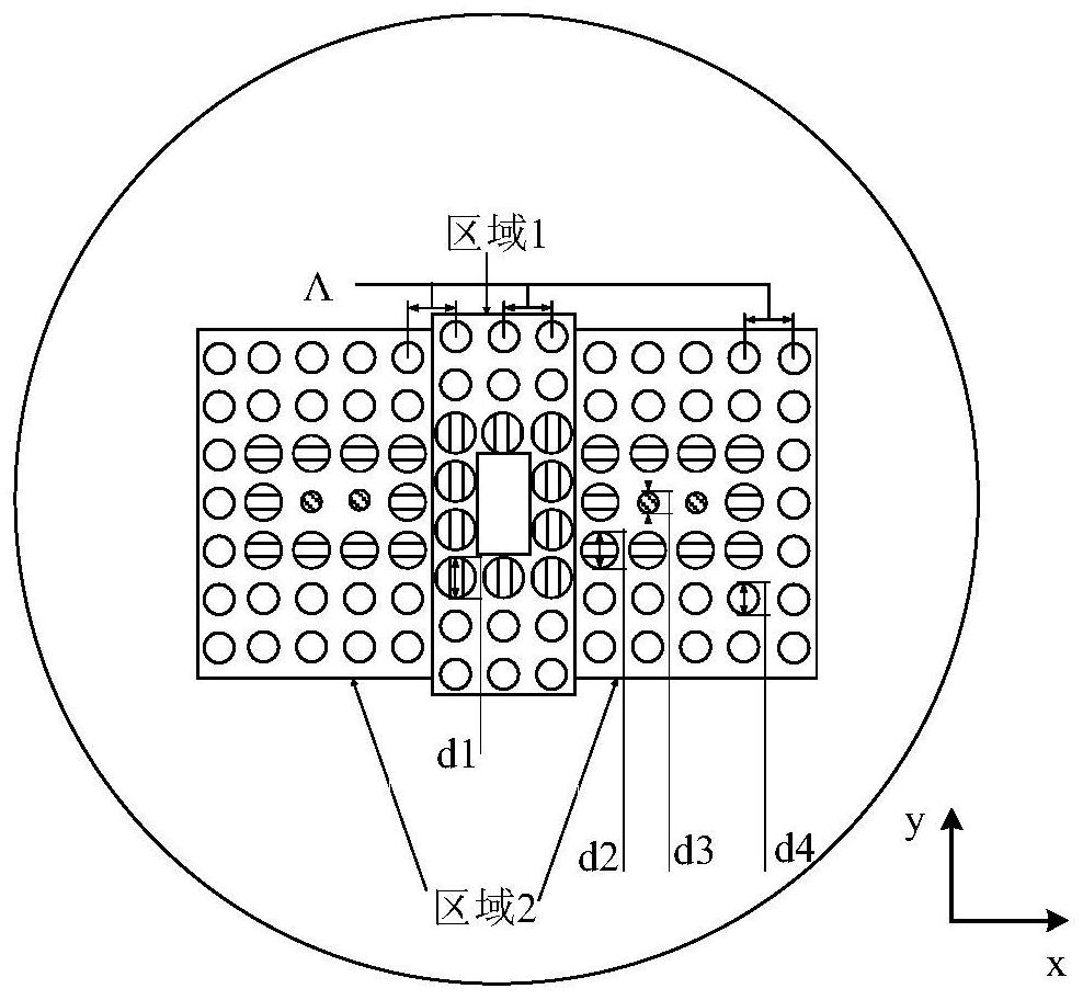
[0069] In this embodiment, the distance Λ between adjacent air holes is 2.288 μm; the diameter d1 of the air holes is 1.601 μm; the diameter d2 of the air holes is 1.372 μm; the diameter d3 of the air holes is 0.224 μm; the diameter d4 of the air holes is 1.055 μm; The number of rows of air holes in the inner cladding air hole array directly above the single-layer air hole array is 2 rows, and the number of air hole rows in the inner cladding air hole array directly below is 2 rows; the air holes contained in the 2 sub-regions of the area 2 air hole array The number of rows is 7 rows and the number of columns is 6 columns.
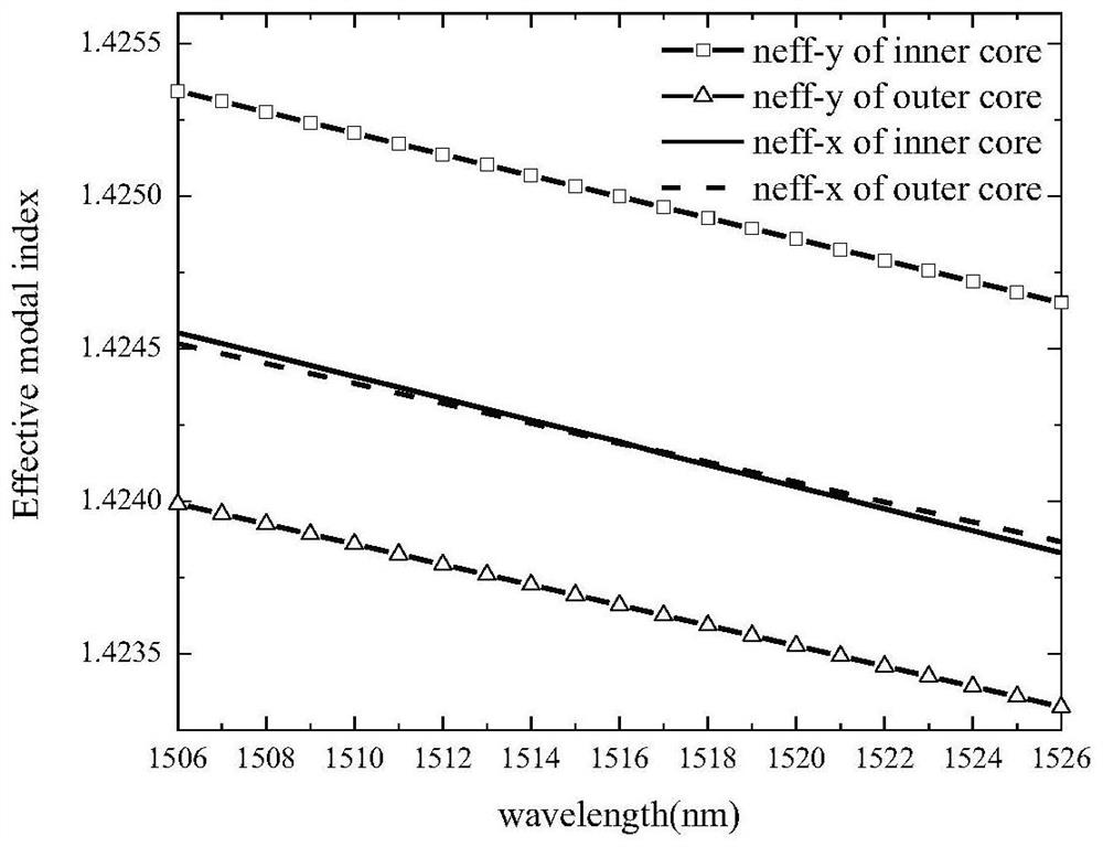
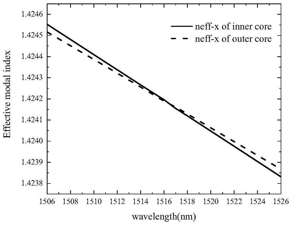
[0070] Referring to Figure 2(a), the value of the inner core neff-y is greater than the value of the inner core neff-x, and the inner core has a birefringence with the x direction as the fast axis and the y direction as the slow axis; the value of the outer core neff-x is greater than The value of neff-y for the outer core, which has birefringence with the...
Embodiment 2
[0074] In this embodiment, the distance Λ between adjacent air holes is 2.293 μm; the diameter d1 of the air hole is 1.606 μm; the diameter d2 of the air hole is 1.377 μm; the diameter d3 of the air hole is 0.229 μm; the diameter d4 of the air hole is 1.060 μm; The number of rows of air holes in the inner cladding air hole array directly above the single-layer air hole array is 4 rows, and the number of air hole rows in the inner cladding air hole array directly below is 4 rows; the air contained in the two sub-regions of the area 2 air hole array The number of hole rows is 11 rows and the number of columns is 7 columns.
[0075] Referring to accompanying drawing 6 (a), the numerical value of inner core neff-y is greater than the numerical value of inner core neff-x, and inner core has x direction as fast axis, and y direction is the birefringence of slow axis; The numerical value of outer core neff-x is greater than The value of neff-y for the outer core, which has birefringe...
Embodiment 3
[0079] In this embodiment, the distance Λ between adjacent air holes is 2.298 μm; the diameter d1 of the air holes is 1.611 μm; the diameter d2 of the air holes is 1.382 μm; the diameter d3 of the air holes is 0.234 μm; the diameter d4 of the air holes is 1.065 μm; The number of air hole rows in the inner cladding air hole array directly above the single-layer air hole array is 6 rows, and the number of air hole rows in the inner cladding air hole array directly below is 6 rows; the air holes contained in the two sub-regions of the area 2 air hole array The number of rows is 15 rows and the number of columns is 8 columns.
[0080] Referring to accompanying drawing 10 (a), the numerical value of inner core neff-y is greater than the numerical value of inner core neff-x, and inner core has x direction as fast axis, and y direction is the birefringence of slow axis; The numerical value of outer core neff-x is greater than The value of neff-y for the outer core, which has birefrin...
PUM
| Property | Measurement | Unit |
|---|---|---|
| diameter | aaaaa | aaaaa |
| diameter | aaaaa | aaaaa |
| diameter | aaaaa | aaaaa |
Abstract
Description
Claims
Application Information
 - R&D
- Intellectual Property
- Life Sciences
- Materials
- Tech Scout
- Unparalleled Data Quality
- Higher Quality Content
- 60% Fewer Hallucinations
Browse by: Latest US Patents, China's latest patents, Technical Efficacy Thesaurus, Application Domain, Technology Topic, Popular Technical Reports.
© 2025 PatSnap. All rights reserved.Legal|Privacy policy|Modern Slavery Act Transparency Statement|Sitemap|About US| Contact US: help@patsnap.com


