Ring Microstrip Waveguide Converter

A waveguide converter, rectangular waveguide technology, applied in waveguide-type devices, circuits, connecting devices, etc., can solve the problems of increasing complexity and loss, limiting the direction of microstrip lines, increasing circuit size, etc., and reducing circuit size. , to avoid over-temperature burn, reduce the effect of loss

Active Publication Date: 2022-04-12
10TH RES INST OF CETC
View PDF12 Cites 0 Cited by
  • Summary
  • Abstract
  • Description
  • Claims
  • Application Information

AI Technical Summary

Problems solved by technology

However, since the end of the microstrip probe inserted into the waveguide is open, it is prone to problems of poor heat dissipation and electric field breakdown and ignition in high-power applications.
And the existing plug-in probe type microstrip waveguide converter, due to the transition from the vertical insertion of the broadside of the rectangular waveguide, thus limits the direction of the microstrip line
If the circuit part is located on the narrow side of the waveguide, you can only turn the microstrip for long wiring, which undoubtedly increases the circuit size, complexity and loss

Method used


Image

  • Ring Microstrip Waveguide Converter
  • Ring Microstrip Waveguide Converter
  • Ring Microstrip Waveguide Converter

Examples


Embodiment Construction

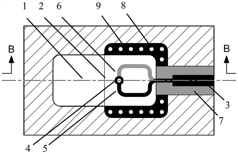
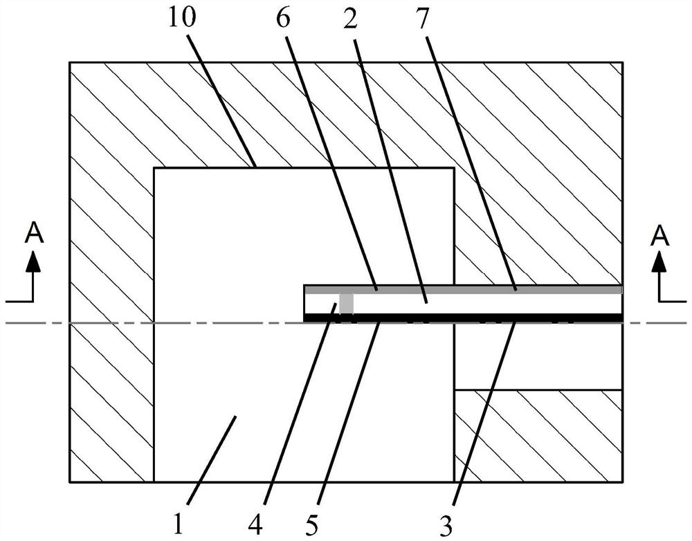
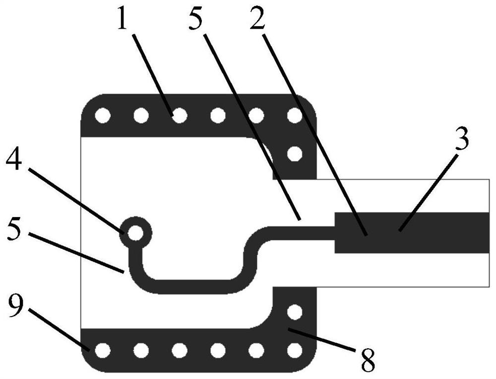
[0018] in such as figure 1 and figure 2 In the shown embodiment, a ring-shaped microstrip waveguide converter includes a rectangular waveguide with a rectangular waveguide cavity 1, and a dielectric substrate 2 inserted into the center of the rectangular waveguide cavity 1 from the connecting window on one side of the rectangular waveguide. On the surface of the dielectric substrate 2 inserted in half of the rectangular waveguide cavity 1, there is a U-shaped opening ground conductor 8 extending and bending along the side wall of the rectangular waveguide cavity 1 and metallized via holes arranged in a linear array in it. 9. The metal ground conductor 7 arranged on the back of the dielectric substrate 2 in contact with the side wall of the rectangular waveguide, and the 50Ω microstrip line 3 along the middle of the front surface of the dielectric substrate 2, is characterized in that the 50Ω microstrip line 3 located on the front surface of the dielectric substrate 2 passes t...


PUM


Abstract

The ring-shaped microstrip waveguide converter disclosed by the invention has high conversion efficiency and wide operating frequency range, can increase power capacity and shorten transmission distance. The present invention is realized through the following technical scheme. The metal ground conductor located on the back of the dielectric substrate is connected to the ∩-shaped microstrip wire through the back of the dielectric substrate, and penetrates into the rectangular waveguide; The hole pads are combined to achieve electrical connection, forming a microstrip closed loop that is isolated by the corresponding coupling of the dielectric substrate. The magnetic field force line of the radio frequency signal passes through the closed microstrip loop, and a current signal is generated in it, and flows into it and extends vertically. The connected 50Ω microstrip line and the metal ground conductor realize the transition from the rectangular waveguide to the microstrip planar circuit, and the magnetic field coupling realizes the high-efficiency conversion of signals between the microstrip line and the rectangular waveguide; the ground conductor passes through the metallized via hole and the metal ground conductor The grounding is electrically connected to shield the radio frequency signal in the ring microstrip waveguide converter.

Description

technical field [0001] The invention belongs to the field of microwave devices, and in particular relates to a broadband rectangular waveguide microstrip conversion technology that can be widely used in the fields of communication, radar, remote measurement and remote sensing, industrial production and the like. Background technique [0002] Microstrip / waveguide transitions are widely used in microwave systems and are key components. Its main indicators: in-band insertion loss and standing wave coefficient, directly affect the noise figure, receiving sensitivity, and transmitting power of the application system. The transmission of radio frequency signals in the waveguide and microstrip must be completed through the waveguide-microstrip transition device. Therefore, the waveguide-microstrip converter is one of the most widely used devices in the microwave system. Its main function is to realize the transmission of microwave signals between the waveguide and the microstrip. ...

Claims


Application Information

Patent Timeline
Patent Type & Authority Patents(China)
IPC IPC(8): H01P5/107
CPCH01P5/107
Inventor 党章刘祚麟李博赵鹏朱海帆黄建
Owner 10TH RES INST OF CETC
Why Eureka
Try Eureka