
High-resolution electromagnetic speaker with bridge edge method

A high-resolution, loudspeaker technology, applied in transformer/inductor coils/windings/connections, magnets, circuits, etc., can solve problems such as bass leakage, reduce sound conversion efficiency, increase magnetic resistance, and reduce bass reproduction limits frequency, increase the sound conversion efficiency, reduce the effect of magnetoresistance

Active Publication Date: 2021-08-13
刘秀珍 +1
View PDF14 Cites 0 Cited by
  • Summary
  • Abstract
  • Description
  • Claims
  • Application Information

AI Technical Summary

Problems solved by technology

[0007] However, for the electromagnetic speaker of Document 1 as described above, the magnetic circuit is provided in a horizontal arrangement structure in which a permanent magnet is placed outside the coil, so it is very unfavorable for the miniaturization of the peripheral size, and there are 3 other than ordinary earphones. Problems with limited applicability of extremely small earphones of ~4mm in-ear insertion type
[0008] In addition, as the driving bias of the vibrating plate, it is necessary to use the outer magnetic field at the upper and lower parts of the permanent magnet assembled outside the upper coil and the lower coil, so there is a problem that the distance between the opposite poles of the permanent magnet is long, and the This increases the reluctance while reducing the sound conversion efficiency
[0009] In addition, after the permanent magnets are inserted outside the coil to form a magnetic circuit, gap guides are provided between the permanent magnets of the magnetic circuit, so only assembly tolerances of the magnetic circuit can occur, and there is a problem that not only is it difficult to maintain the upper Symmetry between the coil and the lower coil, and it may also be difficult to achieve uniformity of sound pressure / characteristics in operation
[0010] In addition, the vibrating plate is supported by an additional upper damper and lower damper-ring, and a gap guide is provided outside the vibrating plate, so there is a problem that the number of parts and assembly processes are many, and gaps may occur The height and size of the shock absorber ring are uneven. If this unevenness occurs, it will not only hinder the uniformity of characteristics / sound pressure / reproduction frequency, but also cause bass leakage.
[0011] In addition, since the vibration plate is a single vibration plate integrated with a plate shape such as a circle or an ellipse, the expansion of the treble and bass ranges is limited. If the vibration plate is set in a dome or conical shape, the full frequency band can be realized. , but due to the strong elasticity of the amorphous alloy material, it is difficult to form and manufacture, so there is a problem of increased manufacturing costs
[0012] In particular, most of the electromagnetic speakers of Document 1 have high resolution, but most of them are not ideal in the amplification performance of the bass and subwoofer, and the treble, midrange, and bass are set separately, and these are combined and arranged to perform Systematization, thereby amplifying frequency and reproducing broadband, due to cost constraints and low sound conversion efficiency, it is difficult to be widely used except for in-ear headphones and hearing aids. Corresponding to the general sound length space of portable, TV, and automobile high-performance speakers

Method used


Image

  • High-resolution electromagnetic speaker with bridge edge method
  • High-resolution electromagnetic speaker with bridge edge method
  • High-resolution electromagnetic speaker with bridge edge method

Examples


Embodiment Construction

[0055] Hereinafter, preferred embodiments of the present invention will be described in detail with reference to the accompanying drawings. For reference, the size of constituent elements, the thickness of lines, and the like shown in the drawings referred to in explaining the present invention are somewhat exaggerated for easy understanding. In addition, the terms used in the description of the present invention are only defined in consideration of the functions performed in the present invention, and may be changed according to the user, operator's intention, custom, and the like. Therefore, definitions of terms should be defined based on the entire contents of this specification.

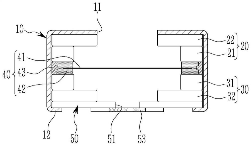
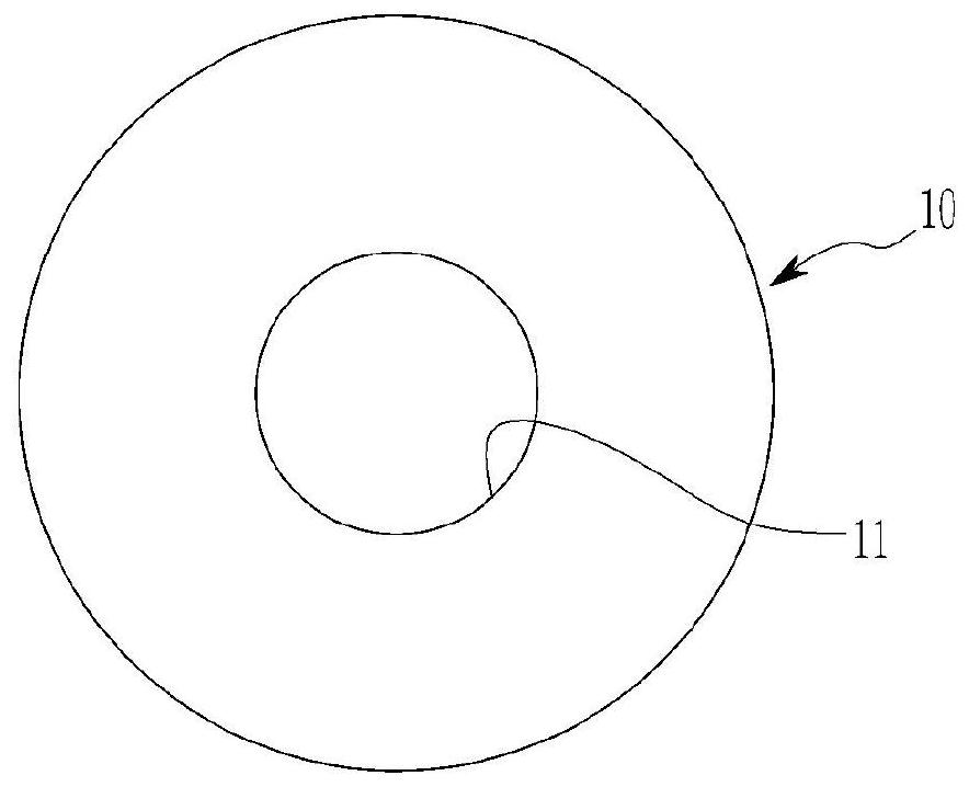
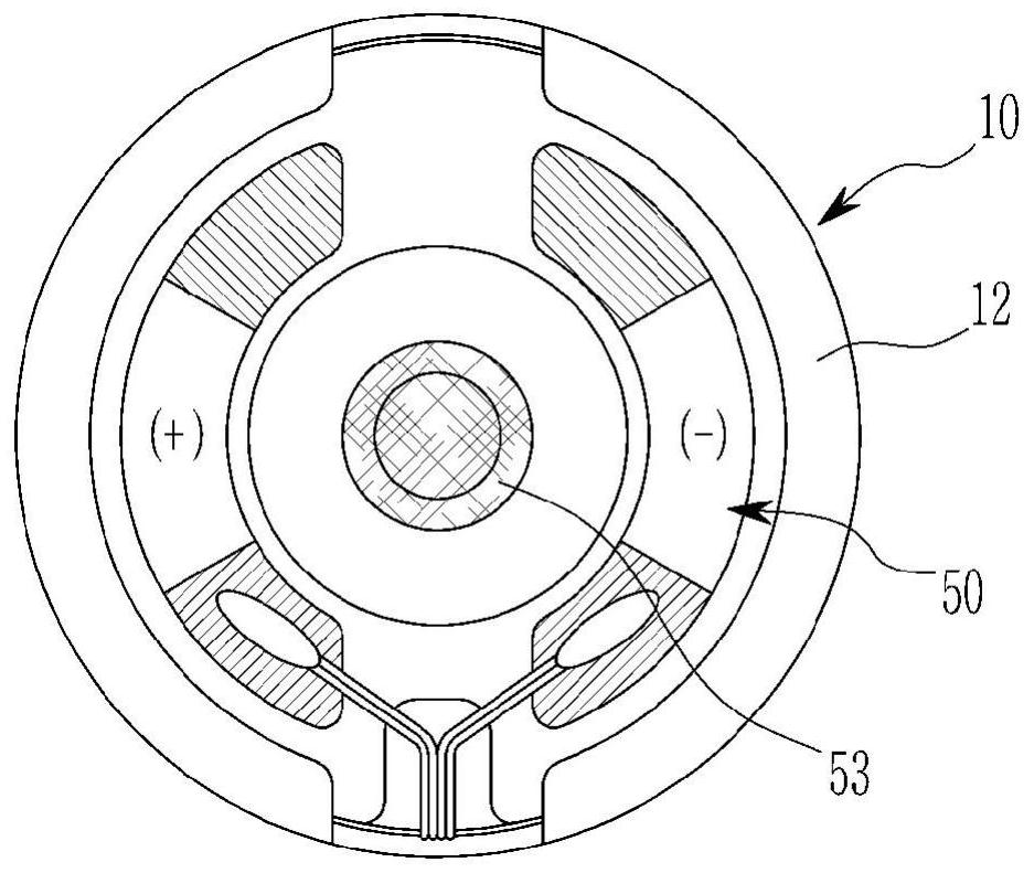
[0056] Figure 1 to Figure 8 It is a drawing shown for explaining a high-resolution electromagnetic speaker of a bridge-shaped edge type according to an embodiment of the present invention. Such a high-resolution electromagnetic speaker of one embodiment is an electromagnetic speaker for a full...


PUM


Abstract

The present invention relates to a high-resolution electromagnetic speaker of a bridge-shaped edge type, in which a coil and a plurality of permanent magnets as a pair of magnetic circuits provided on the upper and lower parts of a vibration module are stacked and arranged in a vertical direction, so that the size and size can be freely reduced and By enlarging the size of the periphery, it can be manufactured into ultra-small earphones inserted into the ear, as well as high-resolution speakers with wide applicability such as portable, TV, and automobile, and the shock absorber for the vibration plate constituting the vibration module is provided. As a magnetic damper, since the reluctance is low and the magnetic damper is in direct contact between the coils without extra space, not only can the magnetic energy of the coil be transmitted to the vibrating plate without loss, but also help It is used to amplify the amplitude of the vibrating plate, thereby increasing the efficiency, and facilitating high-resolution broadband reproduction by amplifying the bass reproduction cut-off frequency.

Description

technical field [0001] The present invention relates to a high-resolution electromagnetic speaker of a bridge-shaped edge type, and more particularly to a high-resolution electromagnetic speaker of a bridge-shaped edge type in which coils and magnetic circuits serving as upper and lower parts of a vibration module are stacked and arranged in a vertical direction. Permanent magnets, so that the size of the periphery can be freely reduced and enlarged, and then it can be manufactured into an in-ear insert-type ultra-small earphone. Through the vibration module composed of a soft and strong magnetic shock absorber, the vibration between the coil and the vibration plate is directly transmitted. Magnetic force, which reduces magnetic resistance and improves sound conversion efficiency, while amplifying bass. Background technique [0002] In general, in an electromagnetic (Electro-magnetic) speaker, the AC magnetic force generated by the coil wound around the wire interacts with t...

Claims


Application Information

Patent Timeline
Patent Type & Authority Patents(China)
IPC IPC(8): H04R9/02H04R9/06H04R7/20H04R7/02
CPCH04R13/00H04R7/04H04R7/06H04R31/003H04R7/22H04R7/20H04R9/025H04R9/06H04R7/02H01F7/02H01F7/081H01F27/28
Inventor 刘秀珍刘守浩
Owner 刘秀珍
Learn More