
Multi-channel capacitance coupling type plasma jet device and working method

A plasma and capacitive coupling technology, applied in the direction of plasma, electrical components, etc., can solve the mutual interference of multiple groups of anodes and cathodes, can not solve the problem of multi-channel jet, can not achieve stable and effective plasma jet, etc., to achieve high efficiency The effect of modification and reasonable structure

Active Publication Date: 2021-11-02
SHANGHAI JIAO TONG UNIV
View PDF17 Cites 0 Cited by
  • Summary
  • Abstract
  • Description
  • Claims
  • Application Information

AI Technical Summary

Problems solved by technology

But the weak point of this patent document is: the device can only regulate the area of ​​the jet, so there is no technical problem that can solve the multi-channel jet
However, the disadvantage of this patent document is that this patent focuses on adjusting the array, and there is a problem that multiple sets of anodes and cathodes interfere with each other, and it cannot realize the combination of plasma jets into jet arrays stably and effectively.

Method used


Image

  • Multi-channel capacitance coupling type plasma jet device and working method
  • Multi-channel capacitance coupling type plasma jet device and working method
  • Multi-channel capacitance coupling type plasma jet device and working method

Examples


Embodiment 1

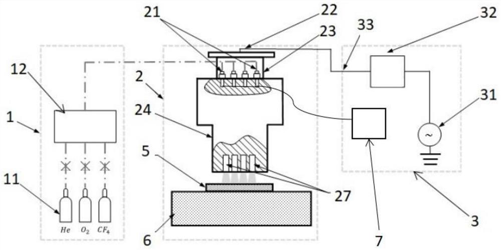
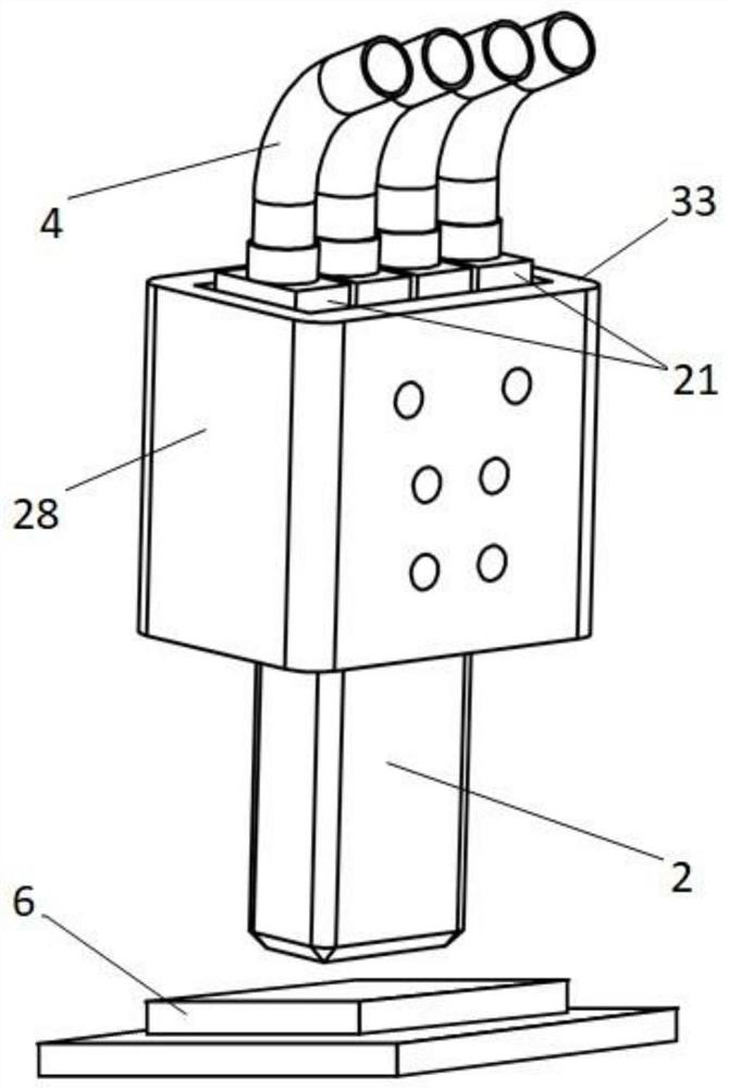
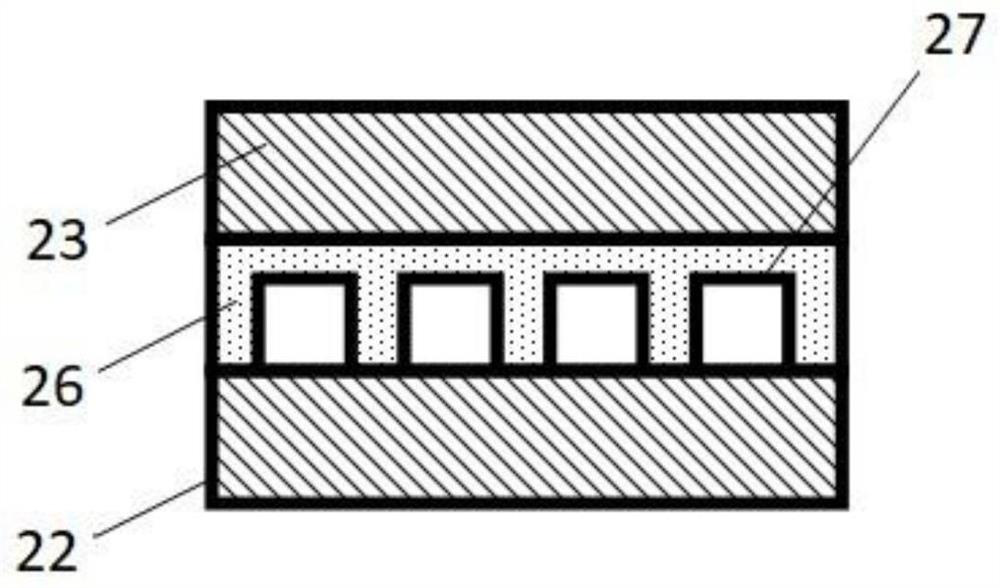
[0056] Such as figure 1 with image 3 As shown, a multi-channel capacitively coupled plasma jet device includes: a gas diversion and mixing structure 1, a plasma generator 2, a radio frequency circuit 3 and an intake pipe 4; the gas diversion and mixing structure 1 passes through the intake The pipeline 4 communicates with the plasma generator 2, the radio frequency circuit 3 is electrically connected to the plasma generator 2, and the anode plate 22, the cathode plate 23 and the insulating medium plate 26 are installed in the plasma generator 2, and the anode plate 22 and the cathode plate 23 are installed The insulating medium plate 26 is provided with a plurality of reaction channels 27 . The gas diversion and mixing structure 1 includes: a gas source 11 and a gas mixing and rectifying device 12. There are multiple gas sources 11. One end of the multiple gas sources 11 is connected to one end of the gas mixing and rectifying device 12 and passes through the gas mixing and ...

Embodiment 2

[0060] Embodiment 2 is a preferred example of Embodiment 1.

[0061] Such as figure 1 As shown, the present invention provides a multi-channel capacitively coupled plasma jet device, including functional components such as a gas diversion and mixing structure 1 , a gas flow control valve 21 , a plasma generator 2 , and a radio frequency power line interface 33 . Among them, the gas diversion and mixing structure 1 is used for the introduction, uniform mixing and air flow rectification of fluorine-containing reaction gas and inert gas; the gas flow control valve 21 is used for real-time control of gas flow into the plasma generator 2 and each of the generators. The flow rate of the reaction channel 27; the plasma generator 2 uses a high-frequency electromagnetic field to excite the inert gas into a plasma state under atmospheric pressure, so that the reactive gas is excited to generate active particles in the plasma active atmosphere; the radio frequency power line interface 33...


PUM


Abstract

The invention provides a multi-channel capacitance coupling type plasma jet device and a working method. The multi-channel capacitance coupling type plasma jet device comprises a gas diversion and mixing structure, a plasma generator, a radio frequency circuit and a gas inlet pipeline, wherein the gas diversion and mixing structure is communicated with the plasma generator through the gas inlet pipeline; the radio frequency circuit is electrically connected with the plasma generator; an anode plate, a cathode plate and an insulating medium plate are mounted in the plasma generator; the insulating medium plate is arranged between the anode plate and the cathode plate and is provided with a plurality of reaction channels. According to the device, the flow of each jet flow unit can be independently controlled, so that the removal function of the linear jet flow can be accurately calculated, regulated and controlled, and the fine and efficient shaping of a complex surface can be realized.

Description

technical field [0001] The invention relates to the design and working method of an atmospheric plasma generating device, in particular to a multi-channel capacitively coupled plasma jet device and a working method. Background technique [0002] Atmospheric plasma processing technology is a new processing method proposed and gradually developed in the 1990s. It is a material removal method of chemical etching. During processing, in the atmospheric environment, some inert gases are ionized to form a plasma state, so that the fluorine-containing reactive gas is excited to form active reactive atoms under this condition, and chemically reacts with the material to be processed to generate gas products to achieve material removal. Atmospheric plasma processing has advantages that other processing methods cannot have at the same time, such as high material removal rate, non-contact processing without subsurface damage, and removal amount can be calculated by theoretical calculatio...

Claims


Application Information

Patent Timeline
Patent Type & Authority Applications(China)
IPC IPC(8): H05H1/26
CPCH05H1/26
Inventor 李洲龙梁锐彬朱利民
Owner SHANGHAI JIAO TONG UNIV
Learn More