Unlock instant, AI-driven research and patent intelligence for your innovation.

System for automatically removing iron impurities in speed reducer lubricating oil and control method thereof

An automatic cleaning and reducer technology, which is applied in the direction of gear lubrication/cooling, mechanical equipment, transmission parts, etc., can solve the problems of gear oil viscosity reduction, affecting the life of the reducer, gear failure of the reducer, etc., to reduce the pumping load , prolong the service life and reduce the rated power effect

Active Publication Date: 2021-11-05
XUZHOU XCMG DRIVELINE TECH CO LTD
View PDF10 Cites 0 Cited by
  • Summary
  • Abstract
  • Description
  • Claims
  • Application Information

AI Technical Summary

Problems solved by technology

However, some iron impurities and other impurities produced during the operation of the reducer will cause the gears of the reducer to fail or even collapse to varying degrees.
In addition, due to the variable load and working conditions of the reducer in construction machinery during use, the temperature in the reducer is high during the working process. Too high temperature leads to a decrease in the viscosity of the gear oil and the failure of the seal. Occurrence of oil leakage and other phenomena, more serious will aggravate gear wear and affect the life of the reducer
[0003] In the prior art, iron impurities are usually removed by magnet adsorption, and a heat exchanger is used to solve the problem of excessive temperature of the lubricating oil, but the lubricating oil must be pumped continuously through the magnetic device and the heat exchanger, which will inevitably lead to the design of the pump High head
In addition, it is difficult to take out iron impurities in the prior art system, and automatic extraction has not been realized

Method used


Image

  • System for automatically removing iron impurities in speed reducer lubricating oil and control method thereof
  • System for automatically removing iron impurities in speed reducer lubricating oil and control method thereof
  • System for automatically removing iron impurities in speed reducer lubricating oil and control method thereof

Examples


Embodiment 1

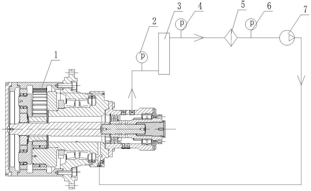
[0039] Such as figure 1 and 2 As shown, this embodiment provides a system for automatically removing iron impurities in the lubricating oil of the reducer, including a controller and a cooling and iron removal device 3 and a pump 7 respectively connected to the controller. The cooling and iron removal device 3 and the pump 7 are sequentially connected to the The reducer 1 is connected to form a closed loop; the cooling and iron removal device 3 includes a housing 3-6, a jacket 3-3, an electromagnet 3-7 and a recovery mechanism; the housing 3-6 is provided with a jacket 3-3, And the cooling chamber 3-4 is formed between the housing 3-6 and the jacket 3-3, and the cooling chamber 3-4 is provided with a circulating coolant, which can be low-temperature water or ice water or cold oil; the electromagnet 3- 7 is installed inside the housing 3-6, the magnetism of the electromagnet 3-7 is adjusted by the controller, and the outside of the electromagnet 3-7 is provided with a magnetic...

Embodiment 2

[0048] This embodiment provides a system control method for automatically removing iron impurities in the lubricating oil of the reducer, including the following steps:

[0049] Such as figure 1 and 2 As shown, the pump 7 works, so that the lubricating oil in the reducer 1 flows into the housing 3-6 of the cooling and iron removal device 3 from the liquid inlet 3-1, and the lubricating oil is cooled by the magnetic fluid 3 on the surface of the electromagnet 3-7. -9 absorbs iron impurities, then flows out from the liquid outlet 3-2, and flows back into the reducer 1 after passing through the filter 5;

[0050] Such as Figure 4 As shown, the sensor installed on the inner wall of the housing 3-6 detects the magnetic field strength of the electromagnet 3-7 radiated by the inner wall of the housing 3-6; When the iron impurities are saturated, the controller stops the pump 7, and the controller controls the valve 3-10 to open, and then controls the hydraulic cylinder 3-13 to sh...


PUM


Abstract

The invention discloses a system for automatically removing iron impurities in speed reducer lubricating oil and a control method thereof.The system comprises a controller, a cooling and iron removing device and a pump, the cooling and iron removing device and the pump are connected with the controller, and the cooling and iron removing device and the pump are sequentially connected with a speed reducer to form a closed loop; the cooling and iron removing device comprises a shell, a jacket, an electromagnet and a recycling mechanism; a jacket is arranged outside the shell, a cooling cavity is formed between the shell and the jacket, and circulating cooling liquid is arranged in the cooling cavity; the electromagnet is installed in the shell, the magnetism of the electromagnet is adjusted by the controller, and magnetic fluid used for adsorbing iron impurities in lubricating oil is arranged outside the electromagnet; and the recycling mechanism comprises a recycling sleeve controlled by the controller, and the recycling sleeve can enter the shell to recycle the magnetic fluid adsorbing the iron impurities and replace the magnetic fluid with a new magnetic fluid. Synchronous cooling can be achieved in the iron impurity removing process, the pumping load is greatly reduced, and the iron impurities can be automatically extracted.

Description

technical field [0001] The invention belongs to the technical field of lubricating oil iron removal devices, and in particular relates to a system for automatically removing iron impurities in lubricating oil of a reducer and a control method thereof. Background technique [0002] The lubricating oil in the reducer in construction machinery can prevent gear tooth surface wear, abrasion, sintering, etc. under normal operation. However, some iron impurities and other impurities produced during the operation of the reducer will cause the gears of the reducer to fail or even collapse to varying degrees. In addition, due to the changeable load and working conditions of the reducer in construction machinery during use, the temperature in the reducer is high during the working process. Too high temperature leads to a decrease in the viscosity of the gear oil and the failure of the seal. Oil leakage and other phenomena will aggravate the wear of the gears and affect the life of the...

Claims


Application Information

Patent Timeline
Patent Type & Authority Applications(China)
IPC IPC(8): F16H57/04
CPCF16H57/0402F16H57/0412Y02P70/10
Inventor 蒋立俏殷浩东曾庆星刘绪德董非尹必峰王建
Owner XUZHOU XCMG DRIVELINE TECH CO LTD