Wavelength multiplexing micro-ring modulator and wavelength locking method

A micro-ring modulator and micro-ring modulation technology, which is applied to instruments, light guides, optics, etc., can solve the problems that the optical splitter and the photoelectric detection PD do not distinguish the wavelength, cannot determine the modulation efficiency of the micro-ring modulator, and reduce the problem, so as to save energy. The effect of demultiplexing device

Pending Publication Date: 2021-11-05
吴弟书
View PDF0 Cites 3 Cited by
  • Summary
  • Abstract
  • Description
  • Claims
  • Application Information

AI Technical Summary

Problems solved by technology

[0003] However, in the wavelength division multiplexing application of existing silicon-based microring modulators, there is no better method for locking the modulation wavelength of different microring modulators: figure 1 It is the wavelength locking method of the existing microring modulator. The incident light signal is modulated by the microring modulator to output the modulated light signal. After the modulated light signal passes through the optical splitter, one-tenth of the light is divided into the photoelectric detection PD, PD Photoelectric conversion generates an electrical signal, which is input to the feedback control circuit, and the feedback control circuit controls the current input to the heating resistor to change the temperature of the micro-ring, so that the modulation efficiency of the micro-ring modulator is always optimal
But this method cannot be used in the micro-ring modulation system of wavelength division multiplexing, such as figure 2 As shown, neither the optical splitter nor the photodetector PD has the function of distinguishing wavelengths, and it is impossible to determine which microring modulator has the modulation efficiency decreased.
[0004] To sum up, in the WDM application of existing silicon-based microring modulators, there is no good method to lock different microring modulation wavelengths

Method used


Image

  • Wavelength multiplexing micro-ring modulator and wavelength locking method
  • Wavelength multiplexing micro-ring modulator and wavelength locking method
  • Wavelength multiplexing micro-ring modulator and wavelength locking method

Examples


Embodiment 1

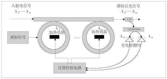
[0049] as the picture shows Figure 8 , the four-wavelength multiplexed optical signal 101 is output to the main waveguide arm 201 of the microring modulator, passing through the microring modulator microring 1-401, microring 2-402, microring 3-403, and microring 4-404 After sequential modulation, a modulated multi-wavelength multiplexed optical signal 102 is generated, and the micro-rings 1-401 modulated by the micro-ring modulate the wavelength 101λ1 in the multi-wavelength signal of the main waveguide arm 201, and the wavelength of the light locked in the micro-ring is λ1, then adjust the coupling coefficient between microring 1 sub-waveguide arm 102 and microring 1-401, the microring 1 modulation wavelength 103 with a wavelength of λ1 can be taken out, and this signal is output to the photoelectric detection PD 405 as a feedback signal. After the conversion, it is input to the feedback control circuit 302, and the current input to the heating resistor 303 is controlled to ...


PUM


Abstract

The invention discloses a wavelength multiplexing micro-ring modulator. The wavelength multiplexing micro-ring modulator comprises a micro-ring modulation main arm, a feedback control circuit unit and n heating resistors, wherein n paths of output ends of the feedback control circuit unit are respectively, correspondingly and electrically connected with the first heating resistor, the second heating resistor... and the nth heating resistor; and the first heating resistor, the second heating resistor... and the nth heating resistor are correspondingly arranged in a first micro-ring modulator, a second micro-ring modulator... and an nth micro-ring modulator respectively. The invention also discloses a wavelength locking method for the wavelength multiplexing micro-ring modulator. The method comprises the steps of S1, modulating a multi-wavelength multiplexing optical signal; S2, acquiring an optical signal of the currently modulated resonant wavelength of each micro-ring; and S3, locking the working wavelength of the micro-ring modulator. The wavelength multiplexing micro-ring modulator and the wavelength locking method have the beneficial effect that a relatively complex and expensive wavelength division demultiplexing device in a traditional wavelength division multiplexing system can be omitted.

Description

technical field [0001] The invention relates to the field of silicon-based modulators in the field of optical fiber communication, in particular to a silicon photonic integrated multi-wavelength control device and method. Background technique [0002] In response to the need to increase the calculation rate of multi-core processors and break through the bottleneck of information transmission rate and power consumption in the future, the industry has proposed a solution to replace electrical interconnection with on-chip optical interconnection. The microring resonator modulator based on the silicon-based photonic integration platform has the characteristics of high integration, low power consumption, and compatibility with CMOS technology. It is currently the most suitable on-chip optical interconnection technology for ultra-short distance transmission. Modulation capability above 50Gbaud symbol rate. [0003] However, in the wavelength division multiplexing application of e...

Claims


Application Information

Patent Timeline
Patent Type & Authority Applications(China)
IPC IPC(8): G02F1/01G02B6/293
CPCG02F1/0147G02B6/29338
Inventor 陈丹郭先会陈志勇
Owner 吴弟书
Why Eureka
Try Eureka