Component, plasma device, and method and device for forming corrosion-resistant coating

A corrosion-resistant coating, plasma technology, applied in coating, ion implantation plating, metal material coating process, etc., can solve the problem that the service life is shorter than expected and has to be replaced or refurbished, increasing operating costs, coating cracking and other problems, to avoid the boundary preferential corrosion phenomenon, prolong the service life, and achieve the effect of consistent corrosion rate

Active Publication Date: 2021-11-05
ADVANCED MICRO FAB EQUIP INC CHINA
View PDF17 Cites 3 Cited by
  • Summary
  • Abstract
  • Description
  • Claims
  • Application Information

AI Technical Summary

Problems solved by technology

In the application of the latest advanced manufacturing process, it is found that the roughness of the workpiece surface will cause plasma to form a large number of growth units on the coating surface, each growth unit includes multiple crystal structures, and the junction of each growth unit and adjacent growth units Downward depression, at the junction of adjacent growth units on the coating surface, the plasma concentration is greater than other areas, so preferential corrosion will occur, and further, infiltration along the growth unit boundary may rapidly corrode the material at the growth unit boundary However, it is detached from the surrounding growth units and falls to form large particle pollutants, causing pollution, which further makes the service life of the workpiece coated with yttrium-containing coating much shorter than expected and has to be replaced or refurbished, which greatly increases the operating cost
[0004] However, due to the huge difference in the thermal expansion coefficient of the coating and the substrate body, when a dense coating is formed on a smooth substrate surface, the coating is prone to cracking and even peeling off.

Method used


Image

  • Component, plasma device, and method and device for forming corrosion-resistant coating
  • Component, plasma device, and method and device for forming corrosion-resistant coating
  • Component, plasma device, and method and device for forming corrosion-resistant coating

Examples


Embodiment Construction

[0049] As mentioned in the background art, the existing corrosion-resistant coatings are prone to particle pollution, and are prone to cracking and falling off. For this reason, the present invention is dedicated to providing a kind of corrosion-resistant coating, and described corrosion-resistant coating is denser, and is difficult for cracking, and corrosion resistance is stronger, and is difficult to form particle pollution, and is described in detail below:

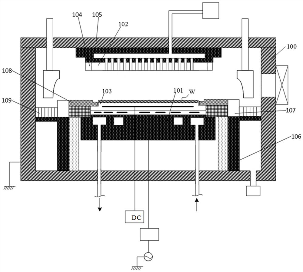
[0050] figure 1 It is a structural schematic diagram of a plasma device of the present invention.

[0051] Please refer to figure 1 , The plasma device includes: a plasma processing chamber 100, the plasma processing chamber 100 is a plasma environment, the semiconductor parts and the inner wall of the plasma processing chamber 100 are exposed to the plasma environment, and the plasma includes F-containing plasma , at least one of Cl-containing plasma, H-containing plasma, or O-containing plasma.

[0052] The plasm...


PUM

PropertyMeasurementUnit
thicknessaaaaaaaaaa
thicknessaaaaaaaaaa
mean roughnessaaaaaaaaaa

Abstract

The invention discloses a component, a plasma device and a method and device for forming a corrosion-resistant coating. The corrosion-resistant coating comprises a part body, wherein the part body comprises a to-be-plated surface, local height deviation of the to-be-plated surface is less than or equal to 20 microns or the average roughness is less than 1 micron in any horizontal distance range of 100 microns; and the corrosion-resistant coating is located on the to-be-plated surface, the local height deviation of the surface of the corrosion-resistant coating within any range of the horizontal distance of 50 micrometers is smaller than or equal to 10 micrometers, and the surface of the corrosion-resistant coating is compact in appearance and free of growth boundaries. The corrosion-resistant coating is high in plasma corrosion resistance and not prone to cracking, and particle pollution is not prone to being formed.

Description

technical field [0001] The invention relates to the field of semiconductors, in particular to a component, a plasma device, a method for forming a corrosion-resistant coating and a device thereof. Background technique [0002] Plasma etching processes play a key role in the field of integrated circuits. The proportion of plasma etching process steps in the latest 5nm semiconductor manufacturing process has increased to more than 17%. The substantial increase in the power and steps of the advanced etching process requires less particle pollution in the plasma etching chamber to further ensure the yield of the etching equipment process. At present, in the most advanced manufacturing process, the requirements for particle pollution have been strict. During the life cycle of the entire component, the particle pollution below 45nm produced is less than 10, and the ground contact rate (zero rate, that is, 45nm particles The probability of 0) is greater than 70%. [0003] At pre...

Claims


Application Information

Patent Timeline
Patent Type & Authority Applications(China)
IPC IPC(8): H01J37/32C23C14/02C23C16/02
CPCH01J37/32495C23C14/022C23C16/0245H01J2237/334
Inventor 段蛟郭盛杨桂林
Owner ADVANCED MICRO FAB EQUIP INC CHINA
Why Eureka
Try Eureka