
Bonding and releasing device for wireless electrostatic chuck, automatic bonding and releasing system for wireless electrostatic chuck and bonding and releasing method for wireless electrostatic chuck

An electrostatic chuck, wireless technology, applied in the application of electrostatic attraction holding devices, circuits, electrical components, etc., can solve the problems of fragmentation, difficult to directly apply high-precision manufacturing process, poor bonding efficiency, etc., to reduce cracking damage Or the occurrence of fragmentation, the effect of reducing the failure rate of bonding and improving the yield of the process

Pending Publication Date: 2021-11-09
STEK CO LTD
View PDF0 Cites 0 Cited by
  • Summary
  • Abstract
  • Description
  • Claims
  • Application Information

AI Technical Summary

Problems solved by technology

[0006] However, such a manual operation method is not only extremely slow, but also because the relative bonding surface of the wireless electrostatic carrier plate and the thinned substrate cannot be guaranteed to be clean and dry under the operation of the personnel environment, resulting in the phenomenon of bonding failure. The bonding operation is repeated, and cracks or fragments may even occur due to misalignment, slippage, or uneven pressing, so the bonding efficiency is extremely poor
Furthermore, since the manual operation is carried out manually, it is difficult for the wireless electrostatic mount plate and the thinned substrate to be accurately aligned during bonding, and it is difficult to be directly applied to the semiconductor process that requires high precision for miniaturization. In the high-precision process, it can only be used in transmission, storage and other occasions that do not require high precision
[0007] In other words, because the existing wireless electrostatic mount plate is bonded to the thinned substrate manually, it not only has the problems of poor efficiency and high failure rate, and may even crack or break, but also cannot meet the high-precision process requirements. How to Solving the aforementioned problems is what the industry expects, and is also the technical problem to be solved by the present invention
[0008] The reason is that the inventors have made in-depth discussions on the problems faced by the existing wireless electrostatic trays when bonding thin substrates, and through the needs of technological development in recent years, through continuous efforts in improvement and trial production, they have finally successfully developed A sticking-off device, an automatic sticking-off system and a sticking-off method for a wireless electrostatic chuck, so as to overcome the shortcomings and inconvenience caused by the existing manual operation

Method used


Image

  • Bonding and releasing device for wireless electrostatic chuck, automatic bonding and releasing system for wireless electrostatic chuck and bonding and releasing method for wireless electrostatic chuck
  • Bonding and releasing device for wireless electrostatic chuck, automatic bonding and releasing system for wireless electrostatic chuck and bonding and releasing method for wireless electrostatic chuck
  • Bonding and releasing device for wireless electrostatic chuck, automatic bonding and releasing system for wireless electrostatic chuck and bonding and releasing method for wireless electrostatic chuck

Examples


Embodiment Construction

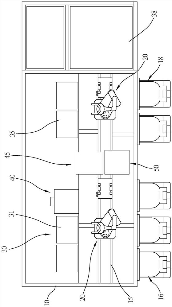
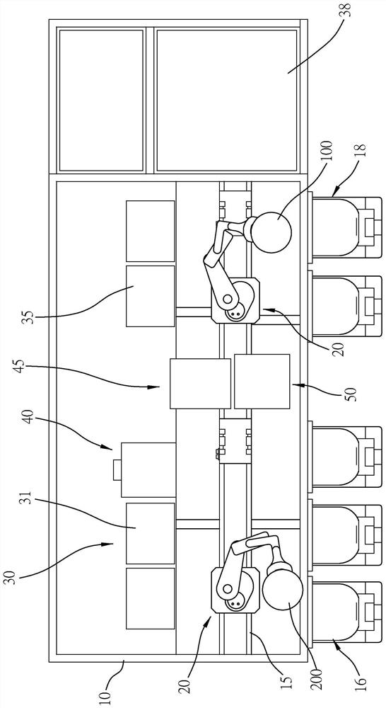
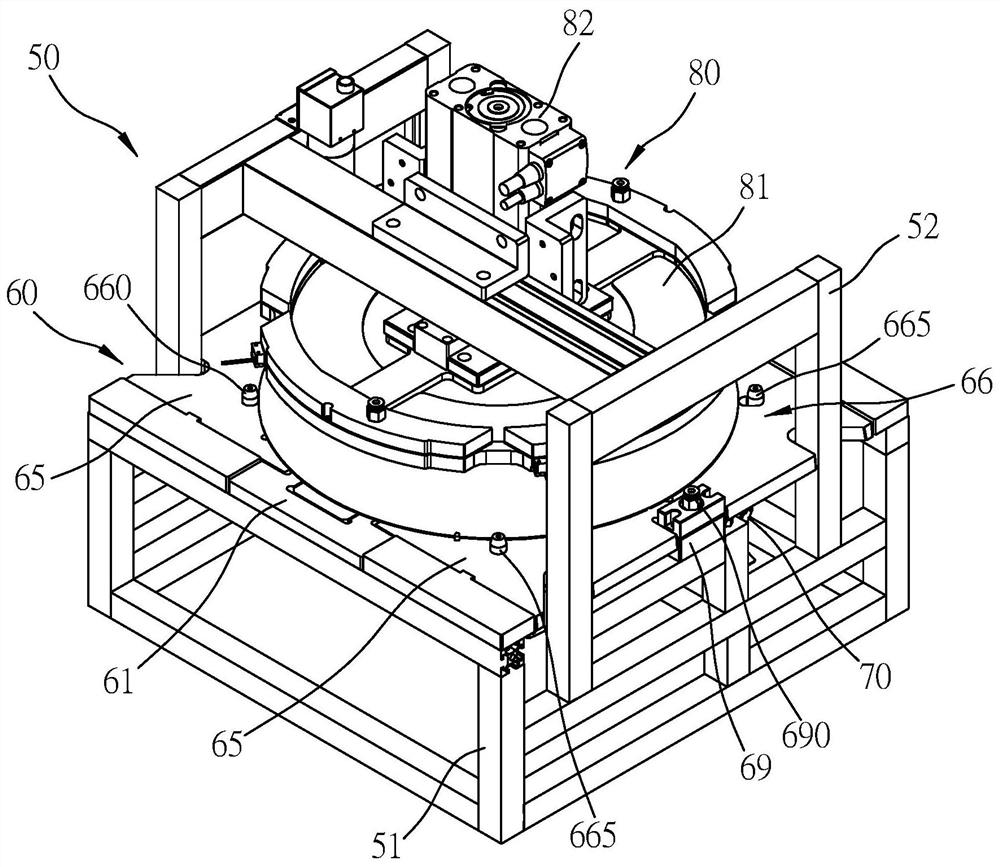
[0047] The present invention is a sticking-off equipment, automatic sticking-off system and sticking-off method for wireless electrostatic chucks. The accompanying drawings illustrate the specific embodiments of the present invention and its components, all about front and back, left and right, and top References to bottom, upper and lower, and horizontal and vertical are for convenience of description only, and do not limit the invention, nor limit its components to any position or spatial orientation. The dimensions specified in the drawings and description can be changed according to the design and requirements of the specific embodiments of the present invention without departing from the patent scope of the present invention.

[0048] The present invention is used for the automatic sticking-off system of wireless electrostatic chuck, then as figure 1 As shown, it is used for automatic bonding and automatic dissociation after bonding of a wireless electrostatic carrier (10...


PUM


Abstract

The utility model relates to a bonding and releasing device for a wireless electrostatic chuck, an automatic bonding and releasing system for the wireless electrostatic chuck and a bonding and releasing method for wireless the electrostatic chuck, which are used for bonding or releasing a wireless electrostatic carrier disc and a thinned substrate. The system comprises a machine body, at least one transmission device, at least one baking device, at least one pre-aligning device and at least one bonding and releasing device. The bonding and releasing device contains a carrier electrostatic generation group for attaching the wireless electrostatic carrier disc and a substrate transfer group displacing relative to the carrier electrostatic generation group so that the substrate transfer group can drive the thinned substrate to be pressed against the surface of the wireless electrostatic carrier disc of the carrier electrostatic generation group. Thus, the carrier electrostatic generation group is driven to enable the wireless electrostatic carrier disc to generate the electrostatic field and to bond the thinned substrate so that bonding efficiency is increased. The requirement with high precision is met to satisfy the automatic manufacturing need for the thinned substrate.

Description

technical field [0001] The invention belongs to an automatic bonding technology for electrostatic chucks, and specifically refers to a sticking-off equipment, automatic sticking-off system and sticking-off method for wireless electrostatic chucks, so that electrostatic chucks can be bonded to thinned substrates such as wafers Automated bonding and dissociation can be performed, which can improve work efficiency and reduce bonding failure and substrate damage, thereby improving the process automation of thinning substrates. Background technique [0002] According to, in recent years, due to the miniaturization development of semiconductor manufacturing process, such as memory and power devices, their miniaturization is developing towards smaller size, higher performance and lower cost, and in order to make the chip area smaller , The design scheme adopted by the semiconductor industry is to replace the original chip design of horizontally deployed chips with a vertical stacki...

Claims


Application Information

Patent Timeline
Patent Type & Authority Applications(China)
IPC IPC(8): H01L21/683H01L21/67
CPCH01L21/6831H01L21/6833H01L21/6835H01L21/67155H01L2221/68381H01L21/67346H02N13/00H01L21/68H01L2221/68318
Inventor 陈明生
Owner STEK CO LTD
Learn More