Puncture surgery robot
A technology of surgical robots and surgical departments, applied in surgical manipulators, surgical robots, surgery, etc., can solve problems such as difficulty in ensuring accuracy, flat scanning, and limited accuracy of positioning and navigation, to achieve improved speed and accuracy, simple device operation, The effect of good promotion value
- Summary
- Abstract
- Description
- Claims
- Application Information
AI Technical Summary
Problems solved by technology
Method used
Image

Examples
Embodiment Construction
[0032] The following will clearly and completely describe the technical solutions in the embodiments of the present invention with reference to the drawings in the embodiments of the present invention.
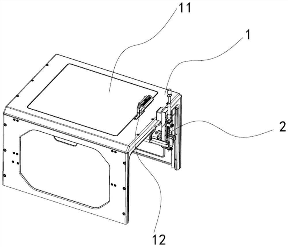
[0033] Such as Figure 1-7 As shown, the present invention provides in order to achieve the above object, the present invention provides the following embodiments: a puncture surgery robot, comprising: a support frame 1, the support frame 1 is used to cover the upper side of the patient, the support frame 1 has a top surface and side surfaces on both sides. The patient lies flat on the bed board of the CT machine, and then the support frame 1 is covered on the patient. The protruding part of the robot's extended arm 4 and the patient's sick part are sent into the CT machine for flat scanning together;
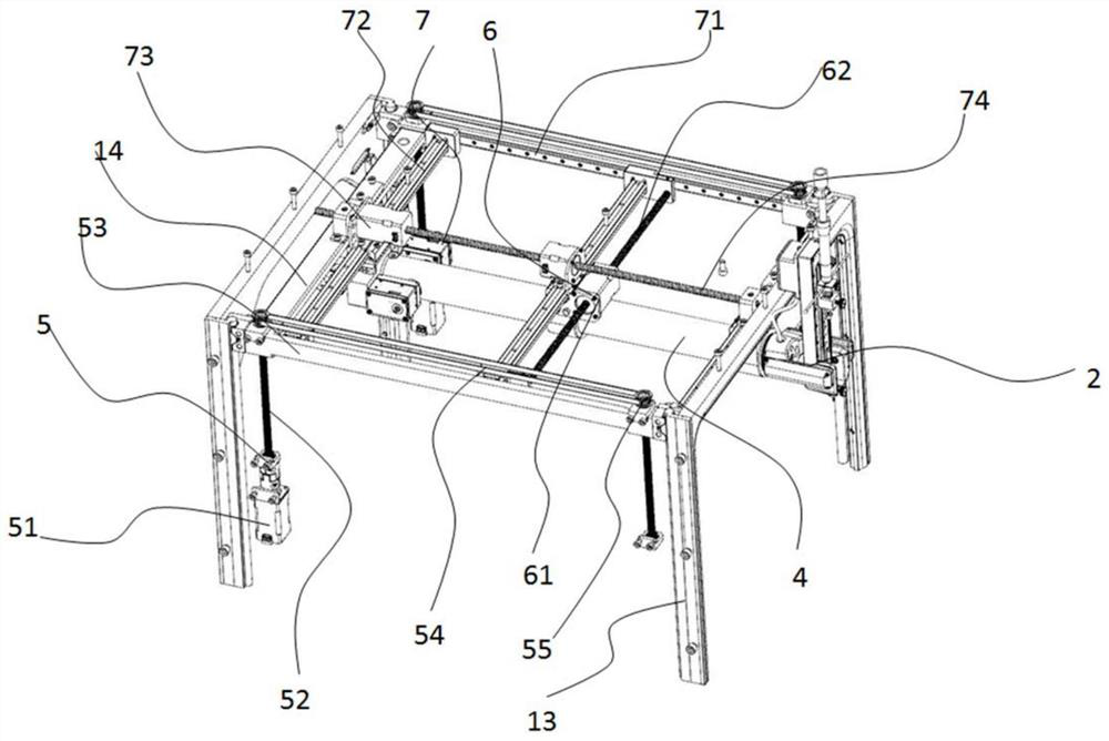
[0034] In the inner lifting drive assembly 5 supporting the outer frame 1, the extending horizontal driving assembly 7 is installed on the lifting driving assembly 5, and is d...
PUM
 Abstract
Description
Claims
Application Information
PatSnap Eureka turns technology decisions into work you can execute. Powered by our Innovation Knowledge Graph, it runs expert workflows across engineering, life sciences, materials and intellectual property. Get your review-ready output in minutes.


