Check patentability & draft patents in minutes with Patsnap Eureka AI!

Exhaust gas trapping device and method

A waste gas and air intake pipeline technology, applied in separation methods, chemical instruments and methods, gas treatment, etc., can solve the problems of reducing gas-liquid contact, uneven distribution of gas-liquid, and affecting absorption effect, etc., to increase the phase interface, Improve mass transfer efficiency and improve absorption effect

Pending Publication Date: 2021-11-12
江苏环保产业技术研究院股份公司
View PDF0 Cites 0 Cited by
  • Summary
  • Abstract
  • Description
  • Claims
  • Application Information

AI Technical Summary

Problems solved by technology

[0003] At present, waste gas absorption devices include packed towers, plate towers, spray towers, etc. according to their structural characteristics. Relatively speaking, packed towers have a simple structure, large gas-liquid contact area, and long contact time. The tower has strong adaptability when the gas volume changes. The flow resistance is small and the advantages are obvious, but its operating range is small and it is particularly sensitive to changes in liquid load. The uneven distribution of gas and liquid in the tower will also reduce the gas-liquid contact to a certain extent and affect the absorption effect

Method used


Image

  • Exhaust gas trapping device and method
  • Exhaust gas trapping device and method

Examples


Embodiment 1

[0030] Example 1 Exhaust gas capture device

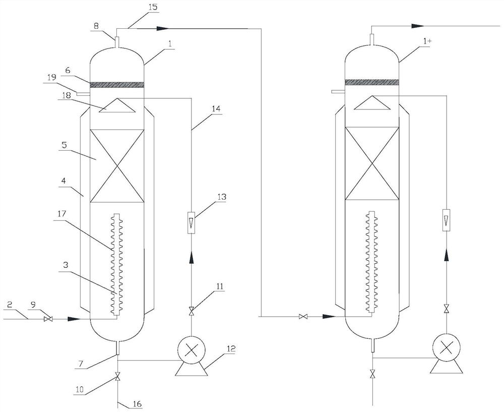
[0031] Exhaust gas capture devices such as figure 1 As shown, including the reaction chamber 1, the height-to-diameter ratio of the reaction chamber 1 is 5-15, the outer wall of the reaction chamber is provided with a heat exchange jacket 4, the middle and lower part of the reaction chamber is provided with an air inlet pipeline 2, and the air inlet pipeline 2 passes through the first valve 9 For control, a gas outlet 8 is provided at the top of the reaction chamber, and a liquid outlet 7 is provided at the bottom, and the liquid outlet 7 is controlled by a second valve 10 . The air intake pipeline 2 is connected to the multi-nozzle injection pipe 3 arranged in the reaction chamber, the multi-nozzle injection pipe 3 is vertically arranged along the longitudinal axis of the reaction chamber, the free end is closed, and the nozzles 17 with a diameter of 1 mm to 5 mm are uniformly distributed on the pipe wall A packing unit 5 is arra...

Embodiment 2

[0033] use figure 1 Exhaust gas capture device for CO in exhaust gas 2 The trapping process includes the following steps: diethanolamine is selected as the absorption liquid, the temperature of the heat exchange jacket is controlled at 15° C., the height-to-diameter ratio of the reaction chamber 1 is 10, and the diameter of the injection nozzle 17 is 2 mm. Before the operation of the device, close the second valve 10 of the liquid outlet, inject a certain amount of absorption liquid, open the third valve 11 and the pump 12 of the liquid circulation pipeline, and control the flow rate; open the first valve 9 of the gas inlet, and the CO 2 The exhaust gas is passed into the reaction chamber, and the liquid is fully contacted with the absorption liquid through the injection nozzle 17, and then enters the packing layer for secondary absorption, and the treated exhaust gas is discharged through the gas outlet. After the absorption liquid is saturated, the third valve 11 and the pu...

Embodiment 3

[0035] use figure 1 The device shown is for use with NH 3 The treatment of low-concentration industrial waste gas includes the following steps: dilute sulfuric acid is selected as the absorption liquid, and only the spray bubbling section can be used to meet the demand. The temperature of the heat exchange jacket is controlled at 5°C, the height-to-diameter ratio of reaction chamber 1 is 8, and the injection nozzle The diameter is 2mm. Before the operation of the device, close the second valve 10 of the liquid outlet, and inject a certain amount of absorption liquid without opening the third valve 11 and the pump 12 of the liquid circulation pipeline; open the first valve 9 of the gas inlet, and the NH 3 The exhaust gas is passed into the reaction chamber, and the liquid is fully contacted with the absorption liquid through the injection nozzle 17 and then discharged through the gas outlet. After the absorption liquid is saturated, open the liquid outlet valve 10 to collect ...


PUM

PropertyMeasurementUnit
diameteraaaaaaaaaa
aspect ratioaaaaaaaaaa

Abstract

The invention belongs to the technical field of waste gas treatment and discloses a waste gas trapping device. The device comprises a reaction cavity, a gas inlet pipeline is arranged on the lower middle portion of the reaction cavity, a gas outlet is formed in the top of the reaction cavity, a liquid outlet is formed in the bottom of the reaction cavity, the gas inlet pipeline is communicated with a multi-nozzle injection pipe arranged in the reaction cavity, and the free end of the multi-nozzle injection pipe is closed. Jet nozzles are distributed on the pipe wall, a filler unit is arranged above the multi-nozzle jet pipe, and a liquid inlet is formed in the side wall of the reaction cavity above the filler unit. The invention further discloses a waste gas trapping method of the device. The trapping device is designed according to the exhaust gas emission characteristics, and the exhaust gas absorption speed process is considered; tiny bubbles generated by spraying can enlarge a phase interface, improve mass transfer efficiency and absorption capacity, and are particularly beneficial to slow reaction; through temperature adjustment, the absorption effect can be further improved. The device can also flexibly select a jet bubbling section or a filler section for treatment according to the property, concentration and the like of waste gas to be treated, thereby saving energy and reducing consumption.

Description

technical field [0001] The invention relates to an exhaust gas collection device and method, belonging to the exhaust gas treatment technology. Background technique [0002] In the context of carbon neutrality, carbon peaking, and high-quality environmental protection, the requirements for the capture, deep treatment, and recycling of waste gas emitted by industrial enterprises are constantly increasing. At present, there are many treatment methods for industrial waste gas, which can be roughly divided into condensation method, absorption method, adsorption method, combustion method, biological method, photocatalytic method and so on. Among them, the chemical absorption method is widely used due to its advantages of wide application range, large absorption capacity, high degree of purification, and strong selectivity, and under certain conditions (high temperature, low pressure, etc.), it can further analyze the exhaust gas and improve the utilization rate of the exhaust gas...

Claims


Application Information

Patent Timeline
Patent Type & Authority Applications(China)
IPC IPC(8): B01D53/78B01D53/75B01D53/58B01D53/62B01D53/52B01D53/18B01D53/14
CPCB01D53/78B01D53/75B01D53/58B01D53/62B01D53/52B01D53/18B01D53/185B01D53/1487B01D53/1475B01D2251/304B01D2251/604B01D2251/506B01D2251/80B01D2252/103B01D2252/20484B01D2252/205B01D2257/304B01D2257/406B01D2257/504
Inventor 吴剑张玲玲章许云陈飞吴海锁张亚一盛夏
Owner 江苏环保产业技术研究院股份公司
Features
  • R&D
  • Intellectual Property
  • Life Sciences
  • Materials
  • Tech Scout
  • Unparalleled Data Quality
  • Higher Quality Content
  • 60% Fewer Hallucinations
Learn More