Desert sand heating system and method

A heating system, desert sand technology, applied in solar heating systems, lighting and heating equipment, solar thermal energy, etc., can solve the problems of long sintering time, fast heat dissipation, low efficiency, etc., achieve good heating effect, short heating time, high heat less loss effect

Active Publication Date: 2021-11-12
LOW SPEED AERODYNAMIC INST OF CHINESE AERODYNAMIC RES & DEV CENT
View PDF18 Cites 0 Cited by
  • Summary
  • Abstract
  • Description
  • Claims
  • Application Information

AI Technical Summary

Problems solved by technology

[0004] However, in the prior art, the heating of desert sand is carried out in an open environment, and there are the following problems: the heat dissipation is fast during heating, and the heat loss is serious, resulting in long sintering time and low efficiency; the size of the heated sand particles is not good The control cannot get the desired target size and cannot meet the needs of the building

Method used


Image

  • Desert sand heating system and method
  • Desert sand heating system and method
  • Desert sand heating system and method

Examples


Embodiment 1

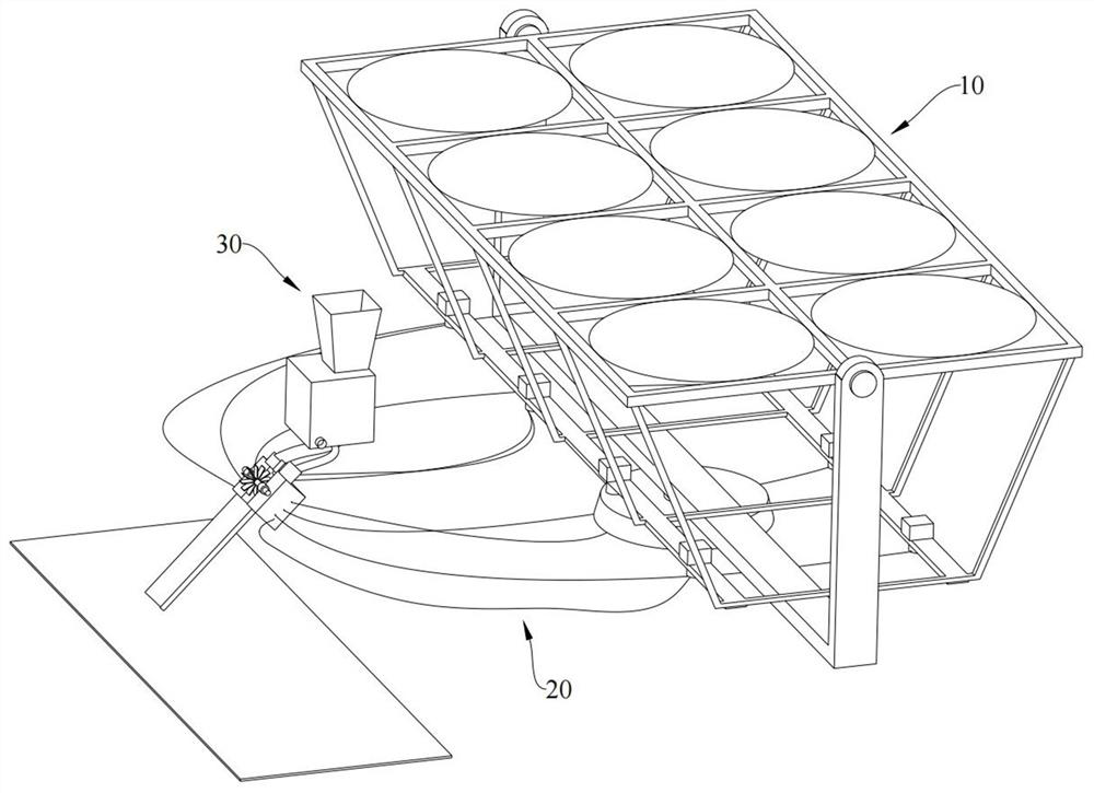
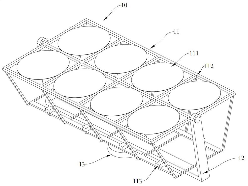
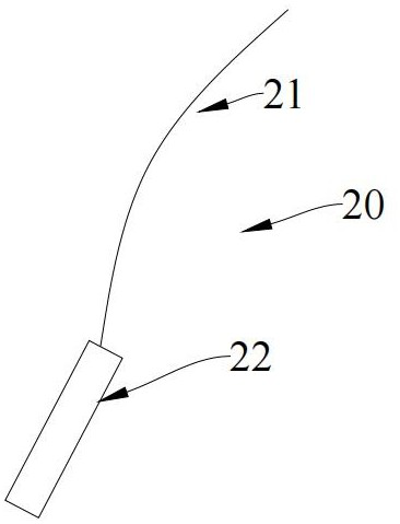
[0042] Such as Figure 1-Figure 7 As shown, Embodiment 1 of the present invention provides a desert sand heating system, including a light concentrating component 10, a light transmission component 20, and a sand melting component 30, and the light concentrating component 10 transmits the collected light through the light transmission component 20 Melting component 30 for sand;

[0043] The sand melting assembly 30 includes a melting device 31 and a classifying device 32;

[0044] The grading device 32 can divide the desert sand into coarse sand and fine sand;

[0045] The melting device 31 includes a melting pool 311 and a scraper member 312. The fine sand can be transported into the melting pool 311 by the first conveying member 321. Grooves 31111 are formed on the surface of the melting pool 311. The coarse sand can be transported by the second transport member 322 into the groove 31111;

[0046] The scraper part 312 is rotatably mounted on the melting pool 311 and locat...

Embodiment 2

[0085] Such as Figure 8 As shown, embodiment 2 of the present invention provides a kind of heating method of desert sand, and described method adopts above-mentioned heating system of desert sand, comprises the following steps:

[0086] Step S10: adjust the light concentrating component 10 to face the sun to obtain light energy; transmit the light energy to the melting pool 311 through the light transmission component 20;

[0087] Step S20: put the desert sand into the feeding device 33, the desert sand enters the classifying device 32 through the feeding device 33, and the desert sand is divided into coarse sand and fine sand by the classifying device 32;

[0088] Step S30: Transport the fine sand to the melting pool 311 for sintering through the first transport member 321, and transport the coarse sand into the groove 31111 of the melting pool 311 through the second transport member, so that the sintered fine sand contacts the coarse sand;

[0089] Step S40: Control the ro...


PUM


Abstract

The invention is suitable for the technical field of casting modeling, and provides a desert sand heating system and method. The desert sand heating system comprises a light gathering assembly, a light transmission assembly and a sand melting assembly, and the light gathering assembly transmits collected light to the sand melting assembly through the light transmission assembly; the sand melting assembly comprises a melting device and a grading device; the grading device can divide desert sand into coarse sand and fine sand; the melting device comprises a melting pool and a scraper component, the fine sand can be conveyed into the melting pool by a first conveying part, a groove is formed in the surface of the melting pool, and the coarse sand can be conveyed into the groove by a second conveying part; and the scraper component is rotatably mounted on the melting pool and is positioned above the groove. According to the method, light gathering and sand melting are mutually independent and free in spatial position, the practicability is high, and the method can be widely used in engineering; and heating is carried out in a relatively closed environment, so that the heat loss is small, and the heating time is short.

Description

technical field [0001] The invention relates to the field of foundry sand, in particular to a heating system and method for desert sand. Background technique [0002] At present, the destruction of nature by humans is becoming more and more serious, and desertification is also becoming more and more serious. It is urgent to control the desert. The development of "sand industry" is a more effective way to solve the current problem of desertification. Therefore, it is of great significance for the sustainable development of society to use desert sand as a raw material and prepare aggregates that can be used in the construction industry after proper heating treatment in deserts and areas near deserts. [0003] As disclosed in the patent CN108160916A: the present invention relates to the preparation of special-purpose coated sand from desert sand, and the production process of the coated sand, which belongs to the field of modeling materials. The invention provides a method for...

Claims


Application Information

Patent Timeline
Patent Type & Authority Applications(China)
IPC IPC(8): F24S23/30B04C9/00B22C5/00B22C5/06
CPCF24S23/30B04C9/00B22C5/00B22C5/06B04C2009/002Y02E10/40Y02P80/20
Inventor 胡站伟宋记峰柳庆林何苗王闻墨张可心
Owner LOW SPEED AERODYNAMIC INST OF CHINESE AERODYNAMIC RES & DEV CENT
Why Eureka
Try Eureka