Optical module

An optical module and optical transmitter technology, applied in the field of optical communication, can solve the problems of increasing the complexity of optical systems and mechanical structures, etc.

Inactive Publication Date: 2021-11-12
HISENSE BROADBAND MULTIMEDIA TECH
View PDF5 Cites 1 Cited by
  • Summary
  • Abstract
  • Description
  • Claims
  • Application Information

AI Technical Summary

Problems solved by technology

In order to reduce the loss caused by the mismatch of the incident angle, special arrangements need to be made in the optical path to generate the corresponding incident angle, which increases the complexity of the optical system and mechanical structure

Method used


Image

  • Optical module
  • Optical module
  • Optical module

Examples


Embodiment 1

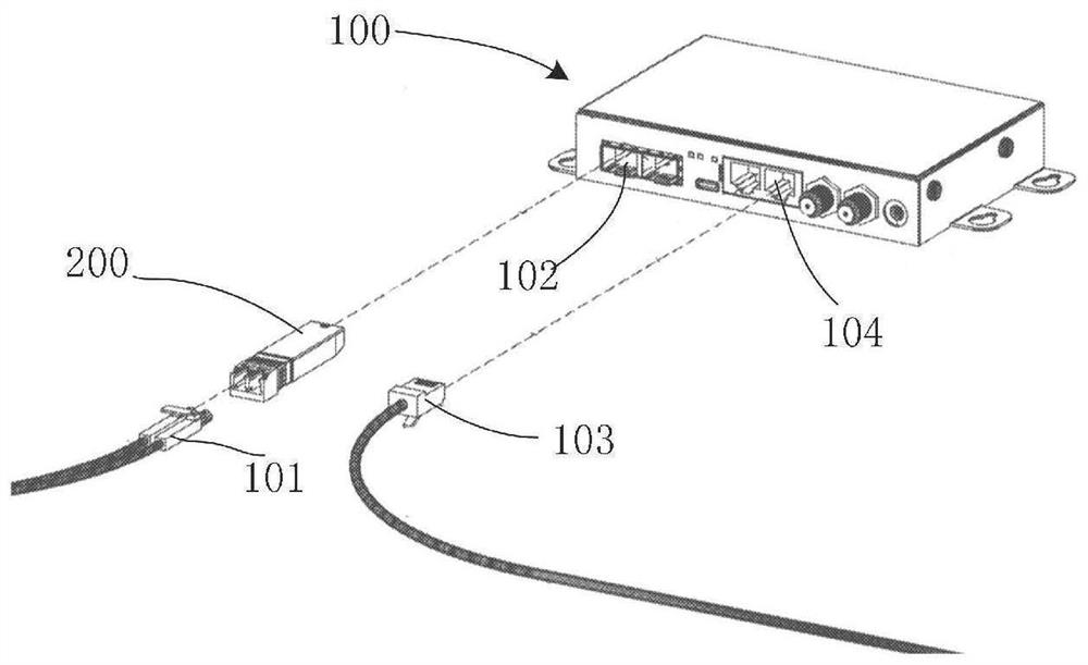
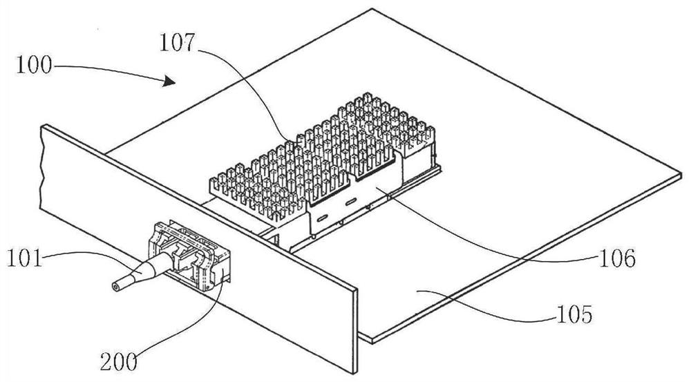
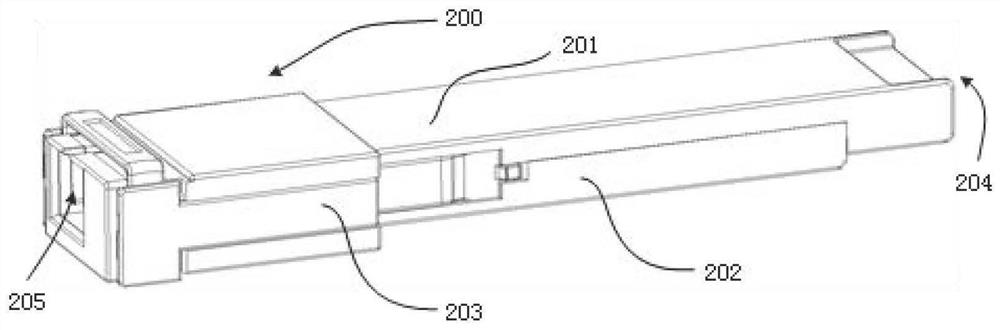
[0058] image 3 It is a schematic structural diagram of an optical module provided by an embodiment of the present invention, Figure 4 A schematic diagram of a disassembled structure of an optical module is provided for an embodiment of the present invention. Such as image 3 , Figure 4 As shown, the optical module 200 provided by the embodiment of the present invention includes an upper housing 201, a lower housing 202, an unlocking component 203, a circuit board 300, and an optical transceiver sub-module 400;

[0059] The upper casing 201 is covered on the lower casing 202 to form a wrapping cavity with two openings; the outer contour of the wrapping cavity generally presents a square body, specifically, the lower casing includes a main board and a wall located at the edge of the main board and perpendicular to the main board. Two side plates are provided; the upper shell includes a cover plate, and the cover plate is covered on the two side plates of the upper shell to...


PUM

PropertyMeasurementUnit
angleaaaaaaaaaa
thicknessaaaaaaaaaa

Abstract

The invention discloses an optical module which comprises a circuit board and an optical transceiver sub-module electrically connected with the circuit board. The optical transceiver sub-module comprises a round square tube body, and an optical transmitter, an optical receiver and an optical fiber adapter which are embedded into the round square tube body. The optical fiber adapter comprises a tube shell and an optical fiber ferrule arranged in the tube shell. The optical fiber ferrule includes an optical fiber. The first end of the optical fiber is bonded with the first end of the glass sheet through refractive index matching glue. In the application, the constraining forces of the glass sheet and the optical fiber on the optical signal are different, and when the incident light enters the first end of the glass sheet, the incident light is emitted. The first end of the optical fiber is bonded with the glass sheet, equivalently, the distance from the incident light to the reflecting surface is increased, and when the incident light is reflected at the second end of the glass sheet, the reflected light is emitted to the edge of the glass sheet, so that the reflected light cannot return along the original path, and the light return loss can be effectively reduced. Only one glass sheet needs to be bonded at the first end of the optical fiber, and special arrangement of an optical path is not needed, so that the complexity of an optical system and a mechanical structure is effectively reduced.

Description

technical field [0001] The present application relates to the technical field of optical communication, and in particular to an optical module. Background technique [0002] In high-speed optical communication products, optical return loss is a key indicator. With the increase of communication rate, the requirements for optical return loss (ORL) are getting higher and higher. For the optical transceiver sub-module with a transmission rate above 25G, the optical return loss requirement has reached -26dB. [0003] In order to meet the requirements of optical return loss, the optical fiber end face of the optical fiber adapter in the traditional optical module is polished at an angle of 4° to 8°. The optical fiber in the fiber optic adapter includes a core layer and a cladding layer, and optical signals are transmitted in the core layer of the optical fiber. Since the end face of the fiber is not perpendicular to the fiber, when the incident light enters the end face of the f...

Claims


Application Information

Patent Timeline
Patent Type & Authority Applications(China)
IPC IPC(8): G02B6/42
CPCG02B6/4246G02B6/428G02B6/4256G02B6/4207G02B6/42
Inventor 吴涛蔚永军濮宏图慕建伟
Owner HISENSE BROADBAND MULTIMEDIA TECH
Why Eureka
Try Eureka