A chamfering tool and chamfering equipment

A technology of chamfering tools and equipment, which is applied in the direction of milling machine equipment, milling machine equipment details, metal processing equipment, etc., can solve the problems affecting the quality of plate coating, film pulling, etc., to increase the installable area, improve cutting accuracy, and simple operation Effect

Active Publication Date: 2022-07-29
WEMHOENER CHANGZHOU MACHINERY MFG
View PDF0 Cites 0 Cited by
  • Summary
  • Abstract
  • Description
  • Claims
  • Application Information

AI Technical Summary

Problems solved by technology

However, during the chamfering process, part of the film will be exposed to the outer edge of the board, and the tool will rub against the film, causing the film to be pulled, which will affect the quality of the film on both sides of the board

Method used


Image

  • A chamfering tool and chamfering equipment
  • A chamfering tool and chamfering equipment
  • A chamfering tool and chamfering equipment

Examples


Embodiment

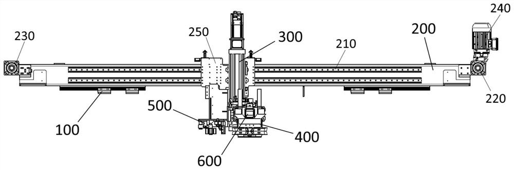
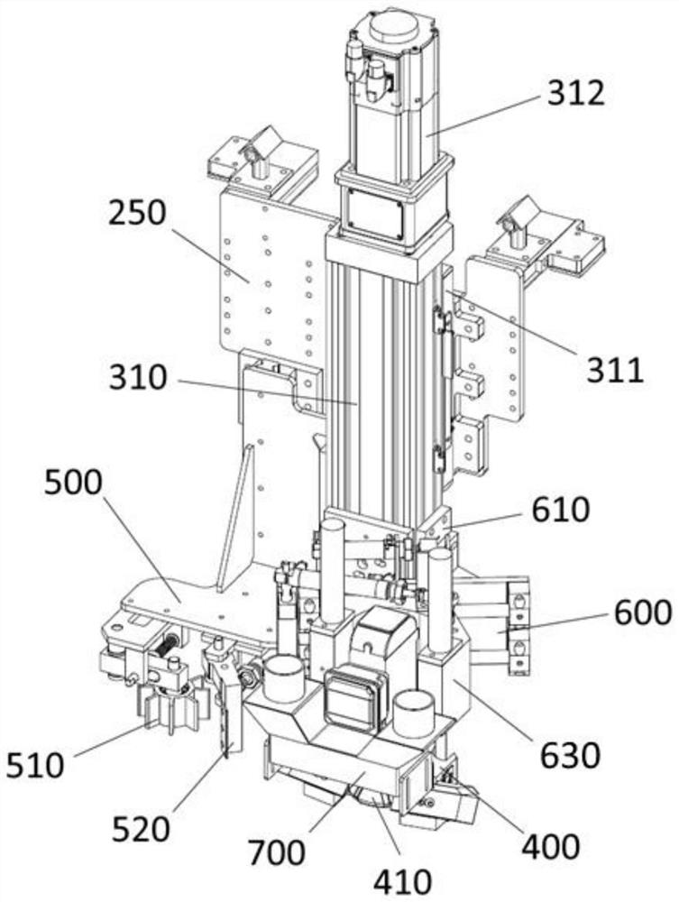
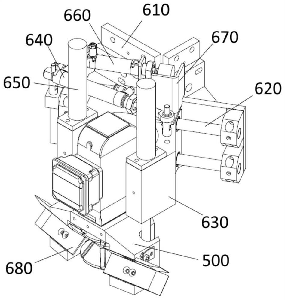
[0061] See attached Figures 1 to 5, a plate chamfering equipment, comprising: a frame 100, a traverse mechanism 200, a lifting mechanism 300, a third mounting seat 400, a conical milling cutter 410, a fourth mounting seat 500, a shredder wheel 510, a scraper 520, a straight line Guide rail 210, driving wheel 220, driven wheel 230, first servo motor 240, first mounting plate 250, electric cylinder 310, slider 311, second servo motor 312, adaptive mechanism 600, first mounting seat 610, guide post 620 , the second mounting seat 630 , the first cylinder 640 , the spring 650 , the second cylinder 660 , the limit plate 670 , the guide plate 680 , the bottom plate 631 , the side plate 632 , and the dust collector 700 .

[0062] Among them, see appendix figure 1 , the frame 100 is used for installing chamfering equipment, and a workbench is arranged at the bottom of the frame 100, and the workbench at least includes a positioning mechanism and a fixing mechanism for the fixed insta...


PUM


Abstract

The invention discloses a chamfering tool and chamfering equipment, which belong to plate chamfering equipment. The chamfering equipment includes a frame, a traverse mechanism that is horizontally installed on the frame and moves linearly parallel to the processing edge of the plate; The lifting mechanism for linear motion, the third mounting seat installed at the output end of the lifting mechanism, the fourth mounting seat located at the output end of the lifting mechanism and located on one side of the third mounting seat; The three mounting seats are provided with two conical milling cutters placed opposite to each other at the top corners; the fourth mounting seat is provided with a shredder wheel and a scraper suitable for cutting the film coated on the board. In the present invention, a shredder wheel and a scraper are arranged in front of the chamfering device, the exposed film in the area to be cut is broken by the shredder wheel, and then the film is removed by the scraper, so as to avoid the conical milling cutter and the conical milling cutter during the chamfering process. The friction between the films affects the quality of the film.

Description

technical field [0001] The invention belongs to plate chamfering equipment, in particular to a chamfering tool and chamfering equipment. Background technique [0002] Chamfering refers to the processing of cutting edges and corners into a certain bevel. Chamfering is to remove burrs from the edge of the metal sheet due to machining, and also to facilitate the assembly of the sheet. The existing chamfering equipment can only perform chamfering processing on one side of the product. After the processing is completed, the plate needs to be turned over to process the other side, and the processing process is relatively cumbersome. [0003] In addition, for some boards, before chamfering, it is necessary to apply film on both sides of the board to improve the smoothness of the board. However, during the chamfering process, part of the film will be exposed to the outer edge of the board, and the cutter will rub against the film, causing the film to be pulled, which will affect t...

Claims


Application Information

Patent Timeline
Patent Type & Authority Patents(China)
IPC IPC(8): B23C3/12B23C9/00B23Q1/25B23Q11/00
CPCB23C3/12B23C9/00B23Q1/25B23Q11/00
Inventor 顾战江海林
Owner WEMHOENER CHANGZHOU MACHINERY MFG
Why Eureka
Try Eureka