
Multi-station bottle blowing machine without moving mold locking frame

A bottle blowing machine and multi-station technology, which is applied in the field of rubber and plastic machinery, can solve the problems of energy waste, large energy consumption, and large motion inertia, and achieve the effects of reducing vibration and energy consumption, increasing single-machine output, and small motion inertia

Pending Publication Date: 2021-11-16
GUANGDONG LESHAN INTELLIGENT EQUIP CORP LTD
View PDF0 Cites 1 Cited by
  • Summary
  • Abstract
  • Description
  • Claims
  • Application Information

AI Technical Summary

Problems solved by technology

But both of these two methods need to move the mold clamping frame. The mold clamping frame is equipped with molds, clamping mechanisms and power devices. It is usually heavy, has a large moment of inertia, and consumes a lot of energy. In addition, in order to pursue output, it requires a higher speed of movement. (For example, the average speed of the translational clamping frame reaches 1 m / s), the driving force required is large, and the braking force required for braking is also large. Frequent starting and braking not only waste a lot of energy, but also cause large vibration and movement If it is unbalanced, it is difficult to further increase the movement speed, that is, it is difficult to increase the production efficiency

Method used


Image

  • Multi-station bottle blowing machine without moving mold locking frame
  • Multi-station bottle blowing machine without moving mold locking frame
  • Multi-station bottle blowing machine without moving mold locking frame

Examples


Embodiment Construction

[0023] The specific implementation manners of the present invention will be further described in detail below in conjunction with the accompanying drawings and embodiments. The following examples are used to illustrate the present invention, but are not intended to limit the scope of the present invention.

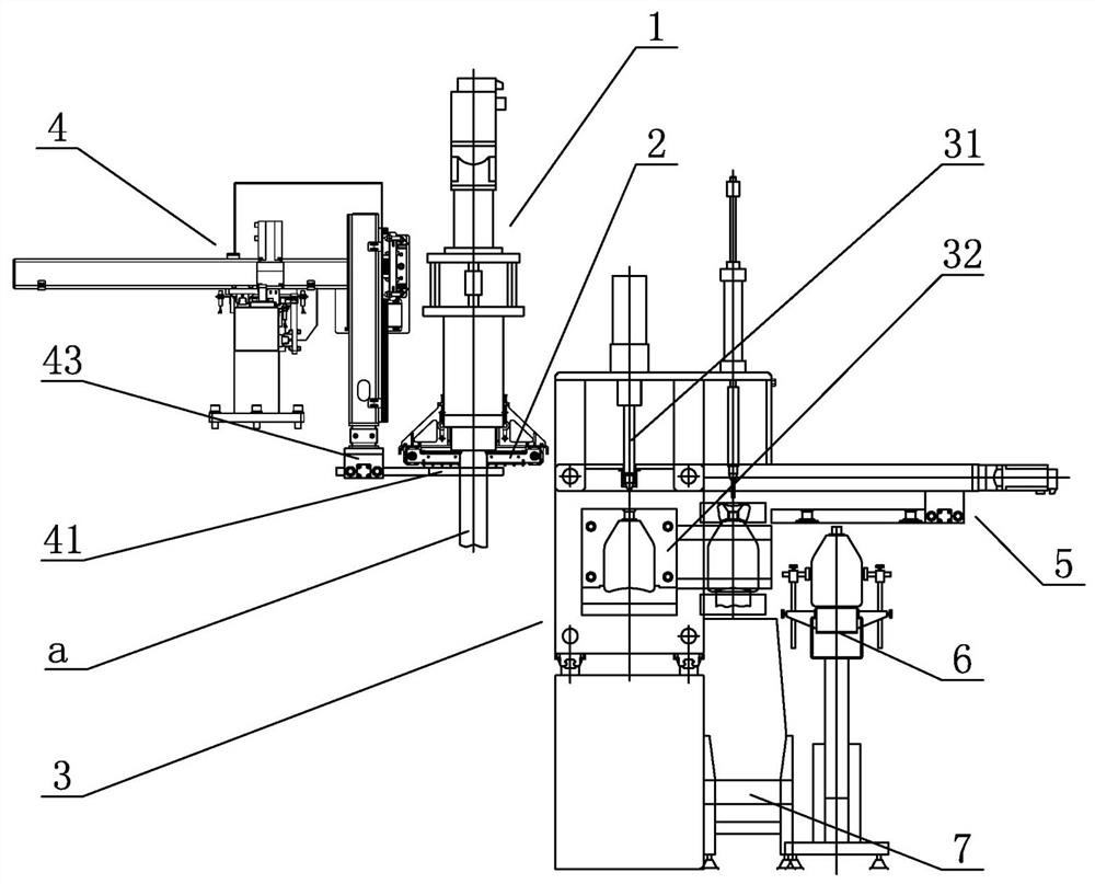
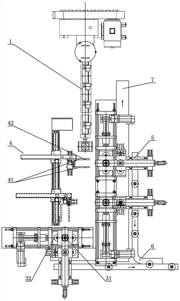
[0024] Such as figure 1 with figure 2 As shown, the multi-station blow molding machine in this embodiment does not move the clamping frame, including an extrusion unit 1, a cutter unit 2, three blow molding units 3, a clamping manipulator unit 4, and a take-off unit. Bottle manipulator unit 5, empty bottle conveyor belt 6 and flash conveyor belt 7.

[0025] The extruding unit 1 has an extruding die and a blowing pipe for extruding a hollow plastic blank tube a.

[0026] The cutter unit 2 is used to cut off the plastic blank tube a.

[0027] The blow molding unit 3 is used for blow molding the plastic blank tube a into a bottle. Each blow molding unit 3 has a frame and...


PUM


Abstract

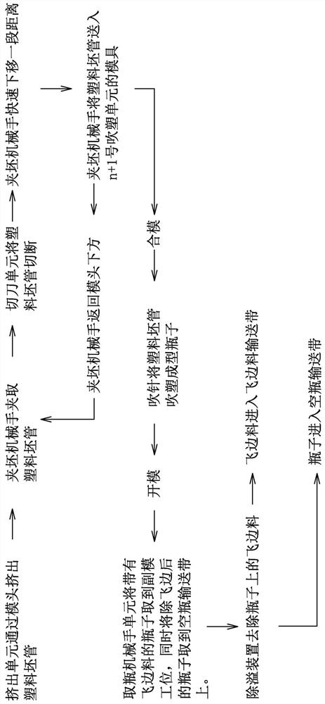
The invention provides a multi-station bottle blowing machine without moving a mold locking frame. The multi-station bottle blowing machine comprises an extrusion unit, a cutter unit, at least two blow molding units, and a blank clamping manipulator unit; the extrusion unit is provided with an extrusion mold head and an air blowing pipe and is used for extruding a plastic blank pipe in a hollow state; the cutter unit is used for cutting off the plastic blank pipe; each blow molding unit is provided with a machine frame and a mold locking frame; the mold locking frames are fixed on the machine frames in a static mode; the mold locking frames are provided with molds; the molds are used for conducting blow molding on plastic blank pipes; and the blank clamping manipulator unit is used for performing reciprocating motion between the extrusion unit and each blow molding unit, clamping the plastic blank pipes extruded by the extrusion unit, keeping the plastic blank pipe s to be hollow and bulged, and sequentially placing the plastic blank pipes into the molds of the blow molding units. According to the machine, the manipulator unit is adopted to clamp the plastic blank pipes and send the plastic blank pipes to the molds of the blow molding units, the mold locking frames do not move in the whole process flow, vibration and energy consumption are effectively reduced, the manipulator unit is small in movement inertia, small in required power, and easy to brake, and high-speed and stable movement of the manipulator unit is easily achieved, so that the single-machine yield is improved.

Description

technical field [0001] The invention belongs to the field of rubber and plastic machinery, and in particular relates to a multi-station bottle blowing machine without moving the clamping frame. Background technique [0002] At present, there are two types of multi-station plastic extrusion blow molding machines on the market: 1) the clamping frame translation method, usually only two stations can be used; 2) the clamping frame rotation method, more stations can be done, There are horizontal rotation and vertical rotation structure. But both of these two methods need to move the mold clamping frame. The mold clamping frame is equipped with molds, clamping mechanisms and power devices. It is usually heavy, has a large moment of inertia, and consumes a lot of energy. In addition, in order to pursue output, it requires a higher speed of movement. (For example, the average speed of the translational clamping frame reaches 1 m / s), the driving force required is large, and the brak...

Claims


Application Information

Patent Timeline
Patent Type & Authority Applications(China)
IPC IPC(8): B29C49/42B29C49/04
CPCB29C49/4252B29C49/04B29C2793/0027B29C49/42069
Inventor 郭锡南高世凡郑俊锋郭锦辉
Owner GUANGDONG LESHAN INTELLIGENT EQUIP CORP LTD
Learn More