
High-temperature optical fiber probe convenient for cooling protection

A fiber optic probe, high temperature technology, applied in the field of infrared detection, can solve problems such as errors, troublesome construction and maintenance, inability to secure certification, etc., to achieve the effects of accurate data, long running time, and error avoidance

Active Publication Date: 2021-11-16
安徽淮光智能科技有限公司
View PDF9 Cites 0 Cited by
  • Summary
  • Abstract
  • Description
  • Claims
  • Application Information

AI Technical Summary

Problems solved by technology

There has always been a large error between theory and experiment, and it is still unable to obtain safety certification in industrial applications
On the other hand, infrared online temperature measurement requires laying and maintaining a large number of long optical fibers on the top of the high-temperature furnace, and the construction and maintenance are very troublesome.

Method used


Image

  • High-temperature optical fiber probe convenient for cooling protection
  • High-temperature optical fiber probe convenient for cooling protection
  • High-temperature optical fiber probe convenient for cooling protection

Examples


Embodiment 1

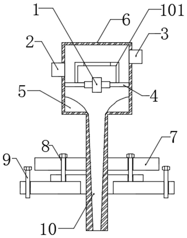
[0029] Such as figure 1 As shown, a kind of high-temperature optical fiber probe that is convenient for cooling protection includes an optical fiber collimator 1, a cooling protection casing 6 and an infrared radiation energy processing system, and the inside of the top of the cooling protection casing 6 is equipped with a first fixing flange 4, the first An optical fiber collimator 1 is installed inside the fixed flange 4, and the optical fiber collimator 1 is installed inside the cooling protective shell 6 through the first fixed flange 4;

[0030] A cooling air source inlet 2 is installed on one side of the cooling protective shell 6, and a high temperature optical fiber outlet 3 is installed on the other side of the cooling protective shell 6. The height of the cooling air source inlet 2 is not higher than the height of the high temperature optical fiber outlet 3.

[0031] In this embodiment, the pins of the detector 13 are connected to a circuit board, and the fiber colli...

Embodiment 2

[0036] Such as Figure 1-2 As shown, a kind of high-temperature optical fiber probe that is convenient for cooling protection includes an optical fiber collimator 1, a cooling protection casing 6 and an infrared radiation energy processing system, and the inside of the top of the cooling protection casing 6 is equipped with a first fixing flange 4, the first An optical fiber collimator 1 is installed inside the fixed flange 4, and the optical fiber collimator 1 is installed inside the cooling protective shell 6 through the first fixed flange 4;

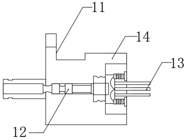
[0037] The infrared radiation energy processing system includes a detector 13, a focusing imaging mirror group 12 and a TE cooling plate. The detector 13 is fixedly installed on a detection base 14, and the bottom of the detection base 14 is equipped with a focusing imaging base 11, and a focusing imaging mirror group 12 One side is installed with a TE cooling plate.

[0038] In this embodiment, a cooling air source inlet 2 is instal...

Embodiment 3

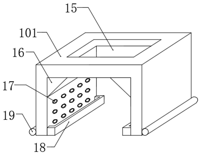
[0046] Such as figure 1 , image 3 with Figure 4 As shown, a kind of high-temperature optical fiber probe that is convenient for cooling protection includes an optical fiber collimator 1, a cooling protection casing 6 and an infrared radiation energy processing system, and the inside of the top of the cooling protection casing 6 is equipped with a first fixing flange 4, the first An optical fiber collimator 1 is installed inside the fixed flange 4, and the optical fiber collimator 1 is installed inside the cooling protective shell 6 through the first fixed flange 4;

[0047] In this embodiment, the infrared radiation energy processing system includes a detector 13, a focusing imaging lens group 12, and a TE cooling plate. The detector 13 is fixedly installed on a detection base 14, and a focusing imaging base 11 is installed on the bottom of the detection base 14. , one side of the focusing imaging lens group 12 is installed with a TE cooling plate.

[0048] In this embodi...


PUM


Abstract

The present invention discloses a high-temperature optical fiber probe convenient for cooling protection. The probe comprises an optical fiber collimator, a cooling protection shell and an infrared radiation energy processing system, a first fixed flange is installed inside the top of the cooling protection shell, and the optical fiber collimator is installed inside the first fixed flange. The optical fiber collimator is installed in the cooling protective shell through a first fixing flange. According to the invention, the optical fiber collimator can be well cooled and protected by using airflow, so that the optical fiber collimator can continuously work in a high-temperature industrial environment; the TE refrigeration patch is used for cooling and protecting the focusing imaging lens group and the detector, so that the detector can work in a room-temperature environment, and after the detector passes through the energy filtering assembly, a detector circuit board can obtain accurate data without temperature drift, continuous and reliable data are provided for a combustion optimization control system, the optimal optimization control effect is guaranteed, and the flue temperature of the coke oven is stable, and energy conservation, consumption reduction and emission reduction are realized.

Description

technical field [0001] The invention relates to the field of infrared detection technology, in particular to the field of temperature detection of a vertical flue installed on the top of a coking furnace, and belongs to the industrial application category of optical temperature measurement and combustion control of coke ovens. Background technique [0002] my country has a large demand for coke production, and the number of coking plants ranks first in the world. However, there are serious defects in the accurate detection of the most important flue temperature parameter of about 1300°C in the coking process. If the flue temperature is unstable, it will lead to uneven heating of the coke oven. , Partial coke formation will cause black smoke when coke is discharged, which directly affects the quality of coke and the life of the furnace body. Optimal control of the heating and combustion process of the coke oven plays a very important role in reducing the production cost of coki...

Claims


Application Information

Patent Timeline
Patent Type & Authority Applications(China)
IPC IPC(8): G01J5/00G01J5/02G01J5/04G01J5/06G01J5/08
CPCG01J5/042G01J5/048G01J5/021G01J5/061G01J5/0018G01J5/0044G01J2005/062G01J2005/0077
Inventor 唐磊张永军张树龙
Owner 安徽淮光智能科技有限公司
Learn More