
Spatial light coupling method and system for special photonic crystal optical fiber

A technology of photonic crystal fiber and coupling system, which is applied in the coupling of optical waveguide, light guide, optics, etc., can solve the problems of low coupling efficiency, low coupling precision, and difficult coupling between special photonic crystal fiber and space light, so as to improve the coupling efficiency , improve the coupling accuracy, and promote the effect of the application

Pending Publication Date: 2021-11-16
XI'AN INST OF OPTICS & FINE MECHANICS - CHINESE ACAD OF SCI
View PDF3 Cites 2 Cited by
  • Summary
  • Abstract
  • Description
  • Claims
  • Application Information

AI Technical Summary

Problems solved by technology

[0005] The purpose of the present invention is to solve the problems that the existing special photonic crystal fiber and space light are difficult to couple, the coupling efficiency is low, and the coupling precision is low, and to provide a space light coupling method and coupling system for special photonic crystal fiber

Method used


Image

  • Spatial light coupling method and system for special photonic crystal optical fiber
  • Spatial light coupling method and system for special photonic crystal optical fiber
  • Spatial light coupling method and system for special photonic crystal optical fiber

Examples


Embodiment Construction

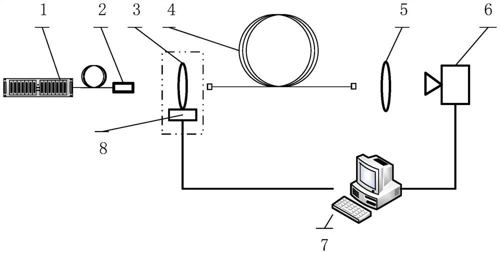
[0027] The present invention will be described in detail below in conjunction with the accompanying drawings and specific embodiments. Those skilled in the art should understand that these embodiments are only used to explain the technical principles of the present invention, and are not intended to limit the protection scope of the present invention.

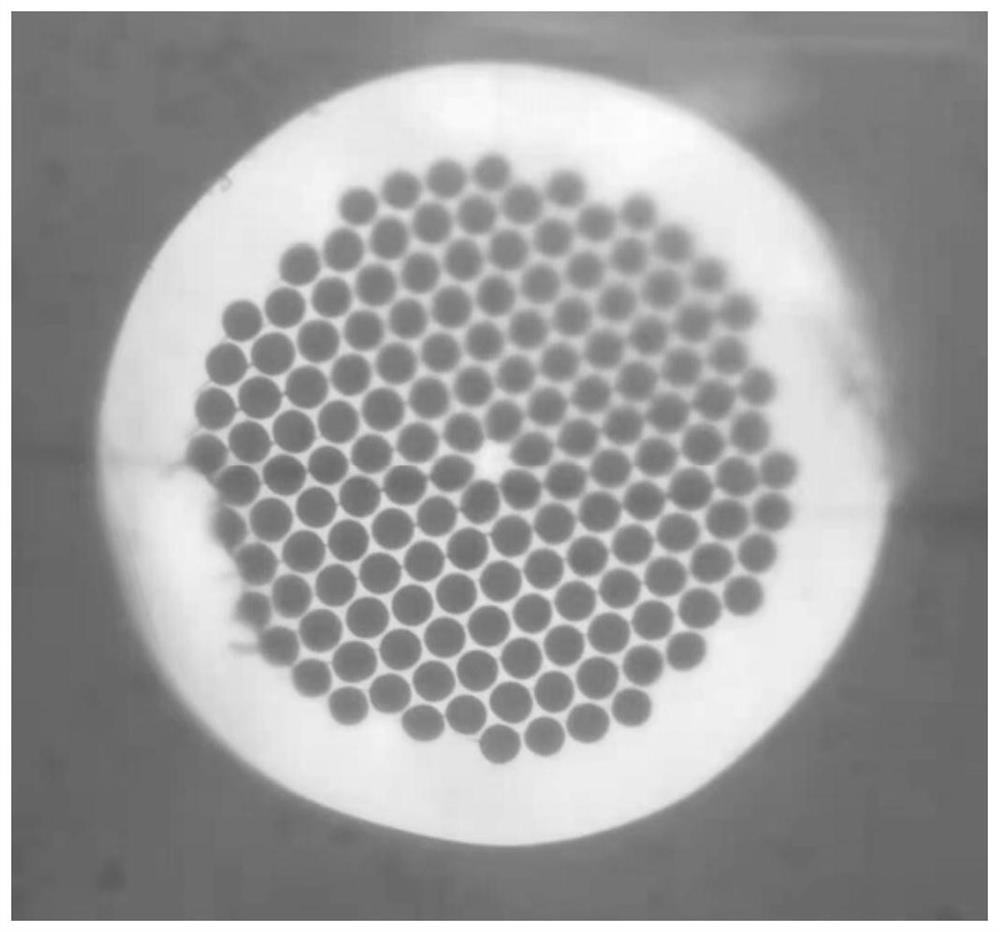
[0028] The invention provides a spatial light coupling method and coupling system for special photonic crystal fibers. The method and system specifically use image contrast technology to couple special photonic crystal fibers and space light, especially for photonic crystal fibers with complex end-face structures. Crystal fiber, such as: "Panda" polarization maintaining photonic crystal, photonic bandgap fiber, kagomé fiber. The proposal of the method improves the working efficiency of the spatial coupling of the special photonic crystal fiber.

[0029] The spatial optical coupling system for special photonic crystal fiber pro...


PUM

PropertyMeasurementUnit
lengthaaaaaaaaaa
wavelengthaaaaaaaaaa

Abstract

The invention provides a spatial light coupling method and system for a special photonic crystal optical fiber, and solves the problems that the existing special photonic crystal optical fiber is difficult to couple with spatial light, the coupling efficiency is low and the coupling precision is low. The spatial light coupling system comprises a laser light source, a light beam collimator, an optical focusing device, a target optical fiber, a three-dimensional adjusting device, an imaging device, a CCD detector and a data processing control device, wherein the light beam collimator, the optical focusing device, the target optical fiber, the imaging device and the CCD detector are sequentially arranged on the emergent light path of the laser light source, the three-dimensional adjusting device is arranged below the optical focusing device and is used for adjusting the position of the three-dimensional space of the optical focusing device, and the data processing control device receives the image acquired by the CCD detector, and compares and processes the acquired image. According to the invention, the position of the three-dimensional space of the optical focusing device is adjusted through the three-dimensional adjusting device, so that the spatial light is injected into the fiber core of the target optical fiber.

Description

technical field [0001] The invention belongs to the field of optical fiber optics, and in particular relates to a spatial light coupling method and a coupling system for special photonic crystal optical fibers. Background technique [0002] Photonic crystal fibers have been widely used in various fields. For example, using rare earth-doped photonic crystal fibers to amplify light pulses to obtain higher energy pulses, using the dispersion shift characteristics of photonic crystal fibers to realize dispersion compensation of ultrashort pulses, using photonic crystal fibers to generate supercontinuum, using photonic bands Gap photonic crystal fiber to realize high power pulse transmission, use photonic crystal fiber to realize gas, pressure test sensor, etc. [0003] Ordinary optical fibers are often connected by fusion splicing, which can form an all-fiber structure, but for the fusion splicing of photonic crystal fibers, especially the fusion splicing of special photonic cr...

Claims


Application Information

Patent Timeline
Patent Type & Authority Applications(China)
IPC IPC(8): G02B6/26G02B6/32G02B1/00
CPCG02B6/262G02B6/32G02B1/005
Inventor 张挺王屹山张伟潘然王振光
Owner XI'AN INST OF OPTICS & FINE MECHANICS - CHINESE ACAD OF SCI
Learn More