Dielectric resonator antenna and terminal

A dielectric resonator and antenna technology, which is applied in slot antennas, antenna supports/installation devices, and antenna grounding switch structure connection, etc., can solve the problems of large size and low gain of millimeter wave antennas

Pending Publication Date: 2021-11-16
HISENSE GRP HLDG CO LTD +1
View PDF0 Cites 2 Cited by
  • Summary
  • Abstract
  • Description
  • Claims
  • Application Information

AI Technical Summary

Problems solved by technology

The millimeter wave antenna in the

Method used


Image

  • Dielectric resonator antenna and terminal
  • Dielectric resonator antenna and terminal
  • Dielectric resonator antenna and terminal

Examples


Embodiment Construction

[0021] Below in conjunction with accompanying drawing, the present invention is described in detail:

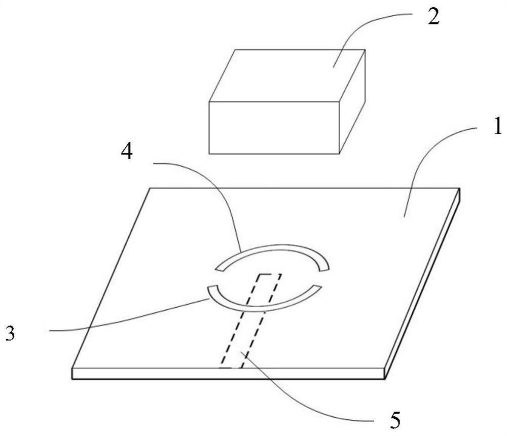
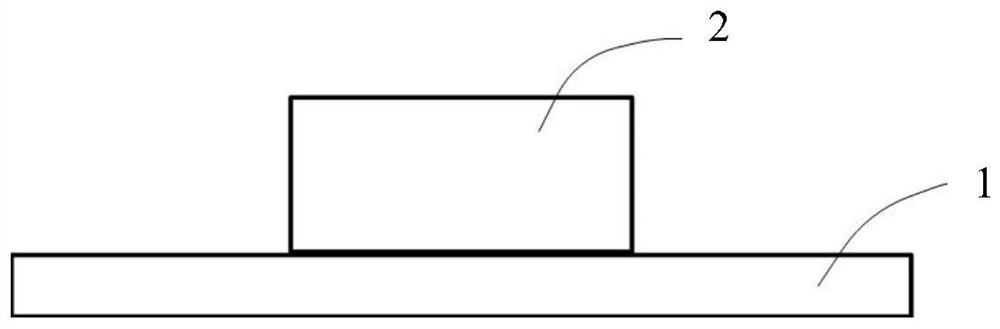
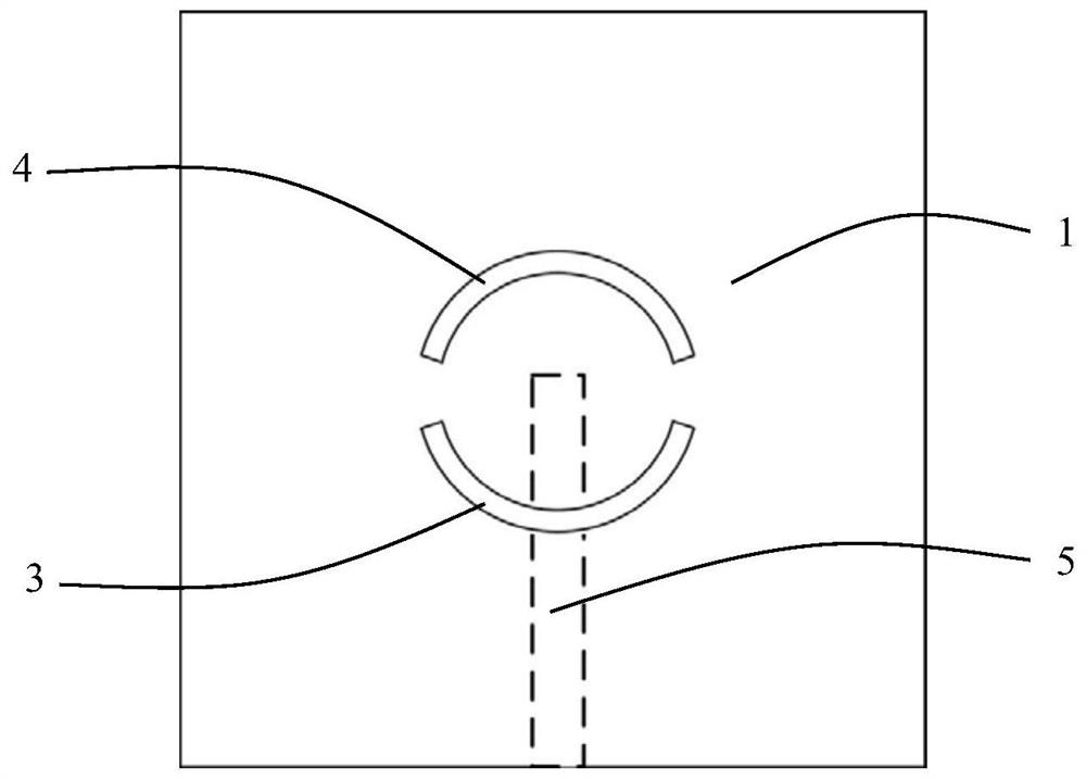
[0022] A dielectric resonator antenna of the present invention, such as Figure 1-Figure 3 As shown, it includes a dielectric substrate 1 and a dielectric resonator 2 disposed on the dielectric substrate. The upper surface of the dielectric substrate 1 is covered with a metal layer, and a coupling gap 3 and a parasitic gap 4 are opened on the metal layer. The dielectric resonator 2 is disposed on the upper surface of the substrate, overlapping with the areas of the coupling slot 3 and the parasitic slot 4 . The feeder 5 is located on the lower surface of the dielectric substrate 1 and is coupled to the coupling slot 3 on the upper surface of the dielectric substrate 1 as a feeder of the dielectric resonator antenna. The coupling slot 3 is a first opening slot, the parasitic slot 4 is a second opening slot, and the opening direction of the first opening slot is opposite to th...


PUM

PropertyMeasurementUnit
Gap widthaaaaaaaaaa

Abstract

The invention discloses a dielectric resonator antenna and a terminal. The dielectric resonator antenna comprises a dielectric substrate and a dielectric resonator arranged on the dielectric substrate; the substrate is provided with a coupling gap, a parasitic gap and a feeder, and the dielectric resonator antenna is characterized in that the coupling gap is a first opening gap; the parasitic slot is a second open slot; the opening direction of the first opening gap is opposite to the opening direction of the second opening gap. According to the dielectric resonator antenna, the coupling slot is the first opening slot, the parasitic slot is the second opening slot, and the opening direction of the first opening slot is opposite to the opening direction of the second opening slot. The first opening gap coupled with the feeder line is used for feeding, high-frequency signals on the feeder line are introduced into the rectangular dielectric resonator, the second opening gap is used for guiding surface current, and finally a needed resonant mode is generated through the rectangular dielectric resonator.

Description

technical field [0001] The invention relates to an antenna, in particular to a dielectric resonator antenna. Background technique [0002] The rapid development of the new generation of mobile communication technology (5G) has put forward more and more stringent requirements for wireless communication equipment. Antenna is one of its key parts, and its performance directly determines the communication quality and user experience. In order to improve the information transmission rate, the operating frequency band of the antenna is raised to the millimeter wave frequency band, and the antenna is often required to have a wider bandwidth and a higher gain. As the frequency increases, the metal loss has a more significant impact on the antenna efficiency and affects the gain of the antenna. At the same time, the space provided by the mobile phone terminal for the millimeter-wave antenna is extremely limited, and the miniaturization and compactness of the antenna is very importan...

Claims


Application Information

Patent Timeline
IPC IPC(8): H01Q13/10H01Q1/22H01Q1/50
CPCH01Q13/10H01Q1/22H01Q1/50
Inventor 张毅陶灵谢倩倩张培冯友怀张燎
Owner HISENSE GRP HLDG CO LTD
Why Eureka
Try Eureka