Implantation instrument with retractable anchoring structure

An anchoring and device technology, applied in the field of medical devices, to achieve the effect of reducing damage, reducing the number of repeated releases, and good positioning effect

Pending Publication Date: 2021-11-19
NINGBO DIOCHANGE MEDICAL TECH CO LTD
View PDF3 Cites 0 Cited by
  • Summary
  • Abstract
  • Description
  • Claims
  • Application Information

AI Technical Summary

Problems solved by technology

[0007] The purpose of the present invention is to overcome the deficiencies of the prior art, and provide an implant device with a retractable anchoring structure for patients with atrial fibrillation who need interventional therapy. The problem of stimulation improves the anchoring effect and reduces the chance of postoperative complications

Method used


Image

  • Implantation instrument with retractable anchoring structure
  • Implantation instrument with retractable anchoring structure
  • Implantation instrument with retractable anchoring structure

Examples


Embodiment 1

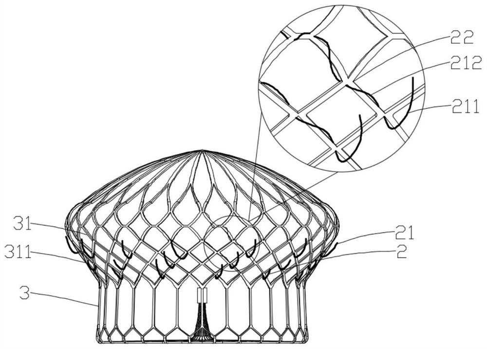
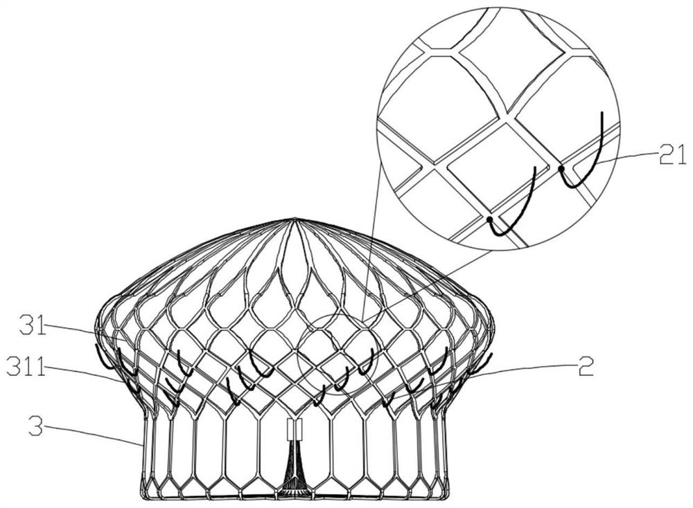
[0072] An implant device with a retractable anchoring structure, the implant device includes a scaffold body, the scaffold body at least includes an anchoring part 2, and the anchoring part 2 includes one or more repeating anchoring units, wherein the anchoring unit includes tissue The contact part 211 and the connecting part 212; the distal part of the tissue contact part 211 can form a hanging anchor with the cavity tissue; when the anchoring unit is radially squeezed, the connecting part 212 undergoes elastic deformation and drives the tissue contact part 211 Together, they shrink inward toward the radial center relative to the main body of the support frame, forming no or low stabbing effect on the tissue in contact with the anchoring part 2 .

[0073] The composition and connection mode of each component in this embodiment will be described in detail below in conjunction with the accompanying drawings:

[0074] In this example, if Figure 1b As shown, the anchoring unit ...

Embodiment 2

[0096] The difference from Example 1 is:

[0097] In this example, if Figure 2a and Figure 2b As shown, the anchoring unit is a shrapnel structure 5, the retracted area and the protruding area are located at the outer side 91, and the retracted area and the protruding area overlap; The other end is free towards the outside of the support frame main body and extends obliquely along the proximal end of the support frame main body. With the central axis of the support frame main body as the center, the elastic sheet structure 5 can be radially moved closer or spread out or bent, so that it has a large Good radial deformation ability, axial support force and bending ability can provide different anchoring angles to adapt to irregular autologous tissue structures.

[0098] In this embodiment, the distal region of the tissue contact portion 211 is provided with a protective structure, and the protective structure includes a ball head 71, such as Figure 2d as shown,

[0099] I...

Embodiment 3

[0104] The difference from Example 1 is:

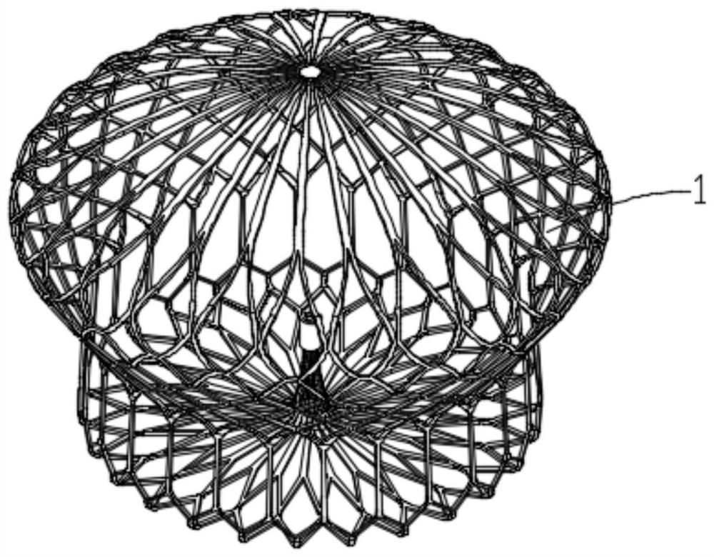
[0105] In this example, if Figure 3a As shown, the implanted device is a left atrial appendage occluder 1, the main body of the support frame includes a self-centered structure, and the self-centered structure includes a central part, and the self-centered structure is formed by the outward divergence of the central part The three-dimensional structure, in the natural unconstrained state, the central piece is located inside the self-centered structure.

[0106] In this embodiment, along the direction in which the central part diverges outward, the self-centered structure includes a proximal connecting rod 61 , a middle independent rod 62 , and a distal ring-shaped body 63 .

[0107] In this embodiment, the three-dimensional structure is "bowl-shaped" in a natural unconstrained state.

[0108] In this embodiment, the three-dimensional structure includes a curled structure with a smaller radius of curvature.

[0109] In this embodim...


PUM


Abstract

The invention relates to the field of medical instruments, and in particular, relates to an implantation instrument with a retractable anchoring structure. The implantation instrument comprises a support frame main body, the support frame main body at least comprises an anchoring part, the anchoring part comprises one or more repeated anchoring units, and each anchoring unit comprises a tissue contact part and a connecting part; the far-end part of the tissue contact part can form hanging anchoring with a cavity tissue; and when the anchoring unit is radially extruded, the connecting part elastically deforms and drives the tissue contact part to retract inwards towards the radial center relative to the supporting frame main body, and the non-puncture or low-puncture effect is formed on the tissue in contact with the anchoring part.

Description

technical field [0001] The invention belongs to the field of medical devices, in particular to an implant device with a retractable anchoring structure. Background technique [0002] Atrial fibrillation (AF for short) is currently the most common sustained or paroxysmal cardiac arrhythmia, affecting approximately 2% of the population worldwide. There are about 10 million patients with atrial fibrillation in my country, and the prevalence rate increases with age, and the incidence rate of people over 65 years old is as high as 84%. Atrial fibrillation is the main risk factor leading to cardiac death and all-cause death. Chronic atrial fibrillation is prone to form left atrial thrombus, causing peripheral arterial thromboembolism. If the thrombus falls off and enters the blood circulation, it will lead to stroke, peripheral blood vessels and organs Embolism and other complications. At the same time, studies have shown that hemodynamic disorders caused by atrial fibrillation ...

Claims


Application Information

Patent Timeline
Patent Type & Authority Applications(China)
IPC IPC(8): A61B17/12
CPCA61B17/12A61B17/12031A61B17/12122A61B17/12177
Inventor 邵烨李彪
Owner NINGBO DIOCHANGE MEDICAL TECH CO LTD
Why Eureka
Try Eureka