
Rapid sample piece manufacturing method for automobile limiting arms

A manufacturing method and a technology for limiting arms, which are applied in the directions of the fastening device of the wing fan, the fastening device of the building, the building, etc., can solve the problems of high position requirements, low processing efficiency, and difficulty in clamping, etc. Reduce processing equipment requirements, improve production efficiency, and ensure the effect of size requirements

Inactive Publication Date: 2021-11-19
ANHUI JIANGNAN MACHINERY
View PDF8 Cites 1 Cited by
  • Summary
  • Abstract
  • Description
  • Claims
  • Application Information

AI Technical Summary

Problems solved by technology

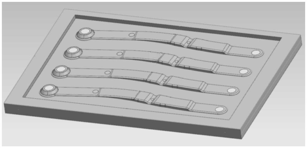
[0002] Automobile limiter arm parts are the main components of car door limiter products. They are characterized by irregular shapes, narrow sides (generally within 15mm), and multi-curved surfaces. Uneven (generally between 5mm-10mm), there are mounting holes at both ends, and the position requirements are high. At present, the samples of this kind of products are limited by the complex shape, and the main processing methods are mostly four-axis or five-axis CNC machining, electric Spark corrosion, etc., can be completed in conjunction with wire cutting and other processes. Since the shapes of the six sides of the parts are irregular, it is less likely to be produced by three-axis CNC.
[0003] At present, the main disadvantages of four-axis and five-axis processing are low processing efficiency and high cost, and because the shape of the part is slender and strip-shaped, it is not easy to clamp, and it is easy to produce the phenomenon of cutting tool during processing, which makes the size difficult to meet the requirements. The stability is poor, and spark corrosion has problems such as poor surface roughness and low efficiency. Due to the constraints of the shape of the part, it is less likely to use three-axis CNC machining

Method used


Image

  • Rapid sample piece manufacturing method for automobile limiting arms
  • Rapid sample piece manufacturing method for automobile limiting arms

Examples


Embodiment Construction

[0031] The following will clearly and completely describe the technical solutions in the embodiments of the present invention with reference to the accompanying drawings in the embodiments of the present invention. Obviously, the described embodiments are only some, not all, embodiments of the present invention. Based on the embodiments of the present invention, all other embodiments obtained by persons of ordinary skill in the art without creative efforts fall within the protection scope of the present invention.

[0032] In describing the present invention, it is to be understood that the terms "opening", "upper", "lower", "thickness", "top", "middle", "length", "inner", "surrounding" etc. Indicating orientation or positional relationship is only for the convenience of describing the present invention and simplifying the description, and does not indicate or imply that the components or elements referred to must have a specific orientation, be constructed and operated in a sp...


PUM

PropertyMeasurementUnit
thicknessaaaaaaaaaa

Abstract

The invention discloses a rapid sample piece manufacturing method for automobile limiting arms. The method specifically comprises the following steps that S1, product modeling is carried out, the plurality of limiting arms are combined and arranged in three-dimensional software, the appearance is manufactured into a standard rectangle, and six surfaces are vertical; S2, numerical control programming is conducted, programming is conducted according to an established data model, the front face and part holes of a blank are simulated and machined firstly, and then the back face of the blank is simulated and machined; S3, blank machining is carried out, the blank is placed in machining equipment to complete the machining process of the front and back surfaces of the blank; and S4, blank cutting is carried out, and the blank is placed in linear cutting equipment and cut to form a sample piece. According to the method, the plurality of parts are arranged in a combined process manner, use of four-axis and five-axis machining center equipment is avoided, the requirement for machining equipment is reduced, the production efficiency is improved, the strength of the parts in the machining process is improved, stability is enhanced, and the size requirement of the parts is ensured.

Description

technical field [0001] The invention relates to the technical field of production and processing of a limit arm, in particular to a rapid sample manufacturing method of an automobile limit arm. Background technique [0002] Automobile limiter arm parts are the main components of car door limiter products. They are characterized by irregular shapes, narrow sides (generally within 15mm), and multi-curved surfaces. Uneven (generally between 5mm-10mm), there are mounting holes at both ends, and the position requirements are high. At present, the samples of this kind of products are limited by the complex shape, and the main processing methods are mostly four-axis or five-axis CNC machining, electric Spark corrosion, etc., can be completed in conjunction with wire cutting and other processes. Since the shapes of the six sides of the parts are irregular, it is rarely produced by three-axis CNC. [0003] At present, the main disadvantages of four-axis and five-axis processing are ...

Claims


Application Information

Patent Timeline
Patent Type & Authority Applications(China)
IPC IPC(8): B23P15/00E05C17/02
CPCB23P15/00E05C17/02
Inventor 余宗文
Owner ANHUI JIANGNAN MACHINERY
Learn More