Autoclaved aerated concrete slab production equipment
A technology for concrete slabs and production equipment, applied to clay preparation devices, mixing operation control, mixing operation control devices, etc., can solve problems such as insufficient mixing, and achieve the effect of ensuring purity, ensuring rigidity, and improving toughness and compactness
- Summary
- Abstract
- Description
- Claims
- Application Information
AI Technical Summary
Problems solved by technology
Method used
Image
Examples
Embodiment 1
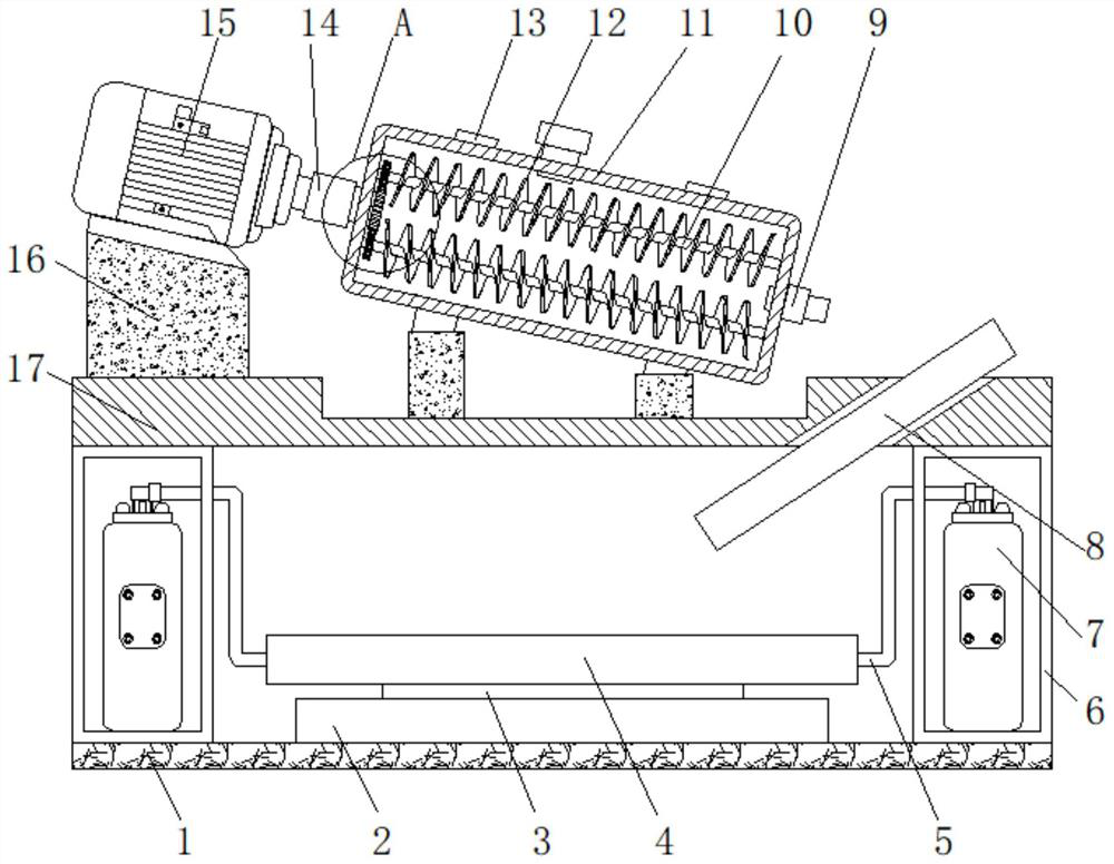
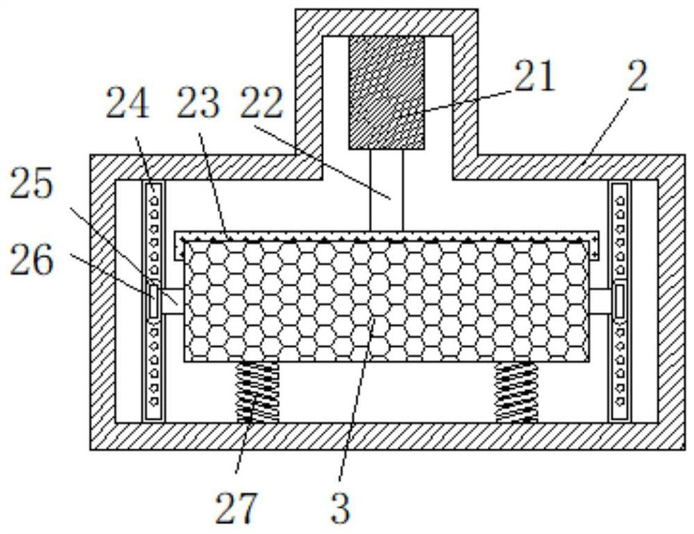
[0030] Example 1: as figure 1As shown in the figure, an autoclaved aerated concrete slab production equipment proposed by the present invention includes a base 1, a sealing box 6 is welded on both sides of the top of the base 1, and a gas tank 7 is fixedly connected to the inner wall of the bottom of the sealing box 6, The output end of the gas tank 7 is fixedly connected with a gas transmission pipe 5 which penetrates and extends to the outside of the sealing box 6. The end of the gas transmission pipe 5 located outside the sealing box 6 is sleeved with the first shell 4, and the top of the base 1 is welded with a frame. 2. A hydraulic cylinder 21 is fixedly connected to the back inner wall of the frame 2, and a hydraulic rod 22 is fixedly connected to the front of the hydraulic cylinder 21. The end of the hydraulic rod 22 away from the hydraulic cylinder 21 is welded with a clamping block 23, and the clamping block 23 is opposite to the movable plate. 3. The fixed clamping i...
Embodiment 2
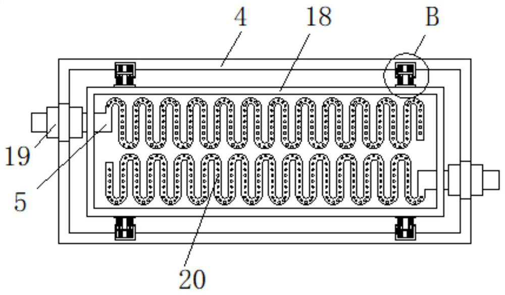
[0031] Example 2: as image 3 , Figure 5 As shown, two boxes 31 are welded to the top and bottom inner walls of the first housing 4, and two second springs 30 are welded to the inner wall of the box 31 close to the first housing 4, and the second springs 30 are close to each other. A sliding plate 32 slidably connected to the inner walls on both sides of the box body 31 is welded on one end of the sliding plate 32 , and two fixing rods 36 penetrating and extending to the outside of the box body 31 are welded on the side of the sliding plate 32 away from the second spring 30 . The fixing rods 36 One end outside the box body 31 is welded with a connecting block 34, the side of the connecting block 34 away from the fixing rod 36 is welded with the outside of the second shell 18, and the side of the connecting block 34 away from the second shell 18 is welded with a sleeve connected to the outer side of the second shell 18. The buffer spring 35 of the outer ring of the fixed rod ...
Embodiment 3
[0032] Example 3: as figure 1 , Figure 4 As shown, a fixed block 16 is welded on the top left of the workbench 17, a drive motor 15 is fixedly connected to the top of the fixed block 16, two inclined steel plates 13 are welded on the top of the workbench 17, and a stirring plate 13 is sleeved inside the inclined steel plate 13. Cylinder 11, the top right side of the table 17 is fixedly connected with a diversion groove 8, the output end of the drive motor 15 is welded with a transmission shaft 14 that penetrates and extends into the mixing cylinder 11, and the transmission shaft 14 is located in the mixing cylinder 11. A second gear 29 is welded on one end of the mixing cylinder 11 , and two rotating shafts 10 are rotatably connected to the inner walls of the mixing cylinder 11 . 28.
PUM
 Abstract
Description
Claims
Application Information
 - R&D
- Intellectual Property
- Life Sciences
- Materials
- Tech Scout
- Unparalleled Data Quality
- Higher Quality Content
- 60% Fewer Hallucinations
Browse by: Latest US Patents, China's latest patents, Technical Efficacy Thesaurus, Application Domain, Technology Topic, Popular Technical Reports.
© 2025 PatSnap. All rights reserved.Legal|Privacy policy|Modern Slavery Act Transparency Statement|Sitemap|About US| Contact US: help@patsnap.com


