Device for measuring inner diameter of through hole of coupling

A technology of inner diameter and laser ranging, which is applied in the field of devices for measuring the inner diameter of through holes of couplings, and devices for measuring the inner diameter of through holes of special threaded couplings, can solve the problems of irregular operation, difficult operation and low operation efficiency, etc. Achieve the effect of avoiding tediousness and errors, increasing accuracy and fast measurement

Pending Publication Date: 2021-11-19
BAOTOU IRON & STEEL GRP
0 Cites 0 Cited by

AI-Extracted Technical Summary

Problems solved by technology

[0002] At present, due to the diameter of the internal through hole of the special threaded coupling (such as figure 1 Φd1) is located in the middle of the coupling, so the measuring claws of conventional vernier calipers cannot reach
At present, the on-site measurement mainly uses the inner diameter micrometer to measure. When inspecting the special threaded coupling of the oil pipe, due to the small inner diameter, it will be difficult to use the inner diameter micrometer to measure the inside of t...

Abstract

The invention discloses a device for measuring the inner diameter of a through hole of a coupling. The device comprises a laser ranging probe, a measurement bracket, a digital display screen, a start button, a reset button, a USB charging port,and a support rod, wherein the digital display screen, the start button, the reset button, and the laser ranging probe form a high-precision laser ranging system, the start button is pressed down outside the coupling, The sum of vertical distances between the probe and the upper and lower inner surfaces of the coupling through hole can be detected by controlling the laser ranging probe, and then the inner diameter of the coupling through hole can be obtained by adding the height of the laser ranging probe. The device provided by the invention is convenient, economical and efficient to use, particularly aims at technical problems of small diameter, difficult operation and inaccurate reading of the small-specification tubing coupling, avoids problems of inaccurate manual measurement and inconvenient operation, and can improve efficiency of production detection.

Application Domain

Technology Topic

Image

  • Device for measuring inner diameter of through hole of coupling
  • Device for measuring inner diameter of through hole of coupling
  • Device for measuring inner diameter of through hole of coupling

Examples

  • Experimental program(1)

Example Embodiment

[0019] The present invention will be described in more detail below with examples. These examples are only descriptions of the best implementation modes of the present invention, and do not limit the content of the present invention in any way.
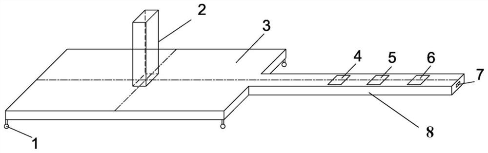
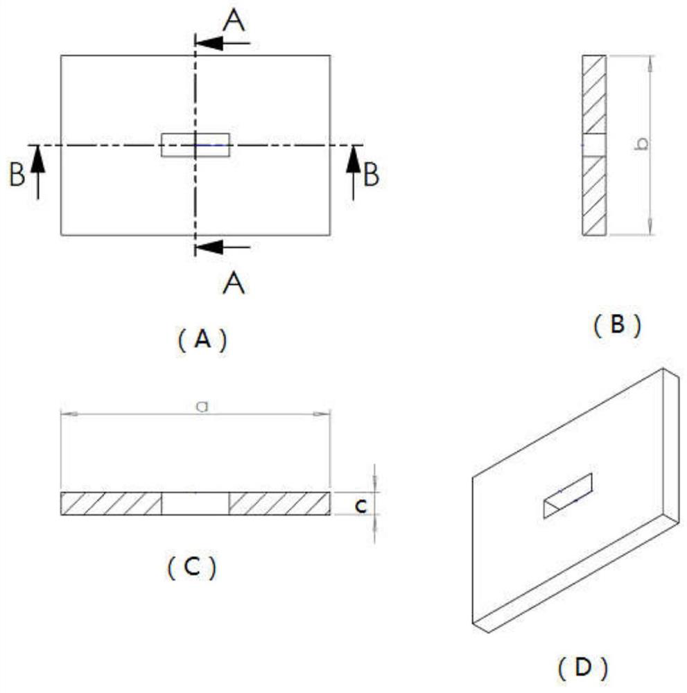
[0020] like figure 2 As shown, it shows a schematic structural view of the device for measuring the inner diameter of the collar through hole provided by the present invention. The device includes a laser ranging probe 2, a measuring bracket 3, a digital display screen 4, a "start" button 5, a reset " "reset" button 6, USB charging port 7, support rod 8, and may also include a measurement bracket contact 1, wherein the measurement bracket 3 and the support rod 8 are fixedly connected to form the device body. like image 3 As shown, a schematic view of the structure of the measuring bracket 3 is shown, which can be a rectangle, wherein A frame is a structural schematic view of the measuring bracket 3, B frame is a schematic cross-sectional structure along the AA line in A frame, and C frame is along the A schematic diagram of the cross-sectional structure of line BB in sheet A, and sheet D is a schematic diagram of the three-dimensional structure of the measuring bracket 3 . It can be seen that a through hole is opened in the center of the measuring bracket 3, and the through hole is used to install the laser distance measuring probe 2. The laser distance measuring probe 2 has two probes arranged at both ends, so when the laser measuring After the distance probe 2 is installed in the through hole of the measuring bracket 3, the laser distance measuring probe 2 can perform distance measuring operations in two directions up and down. There can be 4 measurement bracket contacts 1, which are respectively detachably installed at the four corners of the measurement bracket 3, and the measurement bracket contacts 1 can help the measurement bracket 3 to be concentric with the collar through hole ( That is, the central through hole of the measuring bracket 3 is exactly located at the cross section where the coupling through hole is located. Since the coupling is relatively short, the placement position of the measuring bracket 3 can be determined visually), and it helps to ensure that the laser distance measurement The two ends of the probe 2 are perpendicular to the upper and lower inner surfaces of the collar through hole, which can also avoid the wear of the measuring bracket 3 . The digital display screen 4, the start "start" button 5, the reset "reset" button 6 and the USB charging port 7 are all set on the support rod 8, wherein the digital display screen 4, the start "start" button 5, and the reset "reset" button 6 It is electrically connected with the laser distance measuring probe 2 (for example, the laser distance measuring probe 2 can be electrically connected with the control display system composed of the digital display screen 4, the start "start" button 5 and the reset "reset" button 6 by using wires to realize the start. The "start" button 5 and the reset "reset" button 6 control the operation of the laser distance measuring probe 2, and display the measurement results of the laser distance measuring probe 2 on the digital display screen 4, and the digital display screen 4 can also directly display the collar The measurement results of the inner diameter of the through hole) together form a ranging system. like Figure 4 As shown, when the measuring bracket 3 is placed in the correct position in the through hole of the coupling through the support rod 8, the upper and lower ports of the laser distance measuring probe 2 are facing the position of the through hole of the coupling, and the start can be started by pressing the "start" button 5 The laser distance measuring probe 2 measures the distance between its upper and lower ends to the upper and lower inner surfaces of the collar through hole, and displays the measurement result on the digital display screen 4, according to the laser distance measuring probe 2 on the digital display screen 4 The distance between the two ends from the upper and lower inner surfaces of the collar through hole plus the height of the laser ranging probe 2 itself is the inner diameter of the collar through hole (that is, the inner diameter of the collar through hole = the upper and lower ends of the laser ranging probe 2 respectively The sum of the vertical distances from the upper and lower inner surfaces of the coupling hole + the height of the laser ranging probe 2 itself), or the final inner diameter result of the coupling hole can be directly displayed on the digital display screen 4, and press "reset" Button 6 can re-measure again. The USB charging port 7 is used to charge the measuring equipment composed of the digital display screen 4 , the “start” button 5 , the reset “reset” button 6 and the laser ranging probe 2 .
[0021] In a preferred embodiment of the present invention, as image 3 As shown, the length, width and height of the measuring bracket 3 are a, b and c respectively, and different sizes of measuring brackets can be designed according to the different specifications of the through holes of the coupling (the outer diameter range of the coupling is φ73.02mm-φ365.12mm). Rack 3, the recommended dimensions are shown in Table 1 below.
[0022] Table 1: Measurement Bracket Dimension Recommendations
[0023] Coupling outer diameter range length a(mm) Width b(mm) Thicknessc(mm) 73.02-127mm 60 40 5 127-269.9mm 90 60 5 269.9-365.12mm 180 80 5
[0024] When using the device for measuring the inner diameter of the collar through hole provided by the present invention to measure the inner diameter of the collar through hole, the laser ranging probe 2 (the accuracy of the laser ranging probe 2 should be controlled at 0.1mm, and the height should be controlled within 30mm, ensure the accuracy of the measurement of the inner diameter of the coupling through hole) into the through hole at the center of the measuring bracket 3, and then use the bracket rod 8 to put the measuring bracket 3 with the laser distance measuring probe 2 into the inside of the coupling through hole, and pass The measuring bracket contact 1 makes the measuring bracket 3 concentric with the collar through hole, ensuring that the upper and lower ends of the laser distance measuring probe 2 are respectively facing and perpendicular to the inner surface of the collar through hole. Alternatively, when the specification of the through hole of the coupling is large, the measuring bracket 3 can also be put into the through hole of the coupling through the support rod 8 first, and then the laser distance measuring probe 2 is vertically inserted into the center of the measuring bracket 3 In the through hole, and then realize the measurement of the inner diameter of the coupling through hole. A digital display screen 4, a start "start" button 5 and a reset "reset" button 6 are arranged on the support rod 8, and the ranging operation of the laser distance measuring probe 2 can be controlled by controlling the "start" button 5 on the support rod 8 during measurement. The laser distance measuring probe 2 can be reset by resetting the "reset" button 6, and the USB charging port 7 of the measuring device charges the measuring device through an external power adapter, so that the battery does not need to be replaced frequently.
[0025]Finally, it should be noted that: the above is only a preferred embodiment of the present invention, and is not intended to limit the present invention. Although the present invention has been described in detail with reference to the foregoing embodiments, for those skilled in the art, it still The technical solutions recorded in the foregoing embodiments may be modified, or some technical features thereof may be equivalently replaced. Any modifications, equivalent replacements, improvements, etc. made within the spirit and principles of the present invention shall be included within the protection scope of the present invention.

PUM

no PUM

Description & Claims & Application Information

We can also present the details of the Description, Claims and Application information to help users get a comprehensive understanding of the technical details of the patent, such as background art, summary of invention, brief description of drawings, description of embodiments, and other original content. On the other hand, users can also determine the specific scope of protection of the technology through the list of claims; as well as understand the changes in the life cycle of the technology with the presentation of the patent timeline. Login to view more.

Similar technology patents

Shoot error compensating method and device and weapon system computer

InactiveCN1432786AAccurate shooting errorQuick measurementSighting devicesWeapon control systemsEngineeringData input
Owner:OERLIKON CONTRAVES BESCHRAENKTER HAFTUNG

Crystal prism type beam divergence angle inductor

InactiveCN104251673AQuick measurementLarge Angle Perception RangeUsing optical meansOptical elementsLarge apertureOptical bonding
Owner:QUFU NORMAL UNIV

Classification and recommendation of technical efficacy words

  • Quick measurement
  • Improve accuracy

Vacuum Loss Detection During Laser Eye Surgery

ActiveUS20150190278A1Safe and effective retentionQuick measurementLaser surgeryMedical devicesOcular surgeryEngineering
Owner:AMO DEVMENT

Cassette-based dialysis medical fluid therapy systems, apparatuses and methods

InactiveUS20050209563A1Improvement for dialysisImprove accuracyMedical devicesPeritoneal dialysisAccuracy improvementDialysis
Owner:BAXTER INT INC +1
Why Eureka
Try Eureka