Calculation method for processing radius of plug removal and augmented injection agent

A technology for processing radius and calculation method, applied in the direction of calculation, computer-aided design, special data processing application, etc., can solve the problems of increasing operating costs, waste of chemicals, etc. Effect

Pending Publication Date: 2021-11-19
CHINA OILFIELD SERVICES
View PDF0 Cites 3 Cited by
  • Summary
  • Abstract
  • Description
  • Claims
  • Application Information

AI Technical Summary

Problems solved by technology

If the designed treatment radius of the medicament is larger than required, it will cause waste of medicament and increase the operating cost

Method used


Image

  • Calculation method for processing radius of plug removal and augmented injection agent
  • Calculation method for processing radius of plug removal and augmented injection agent
  • Calculation method for processing radius of plug removal and augmented injection agent

Examples


Embodiment 1

[0048] 1) Determine the specific interval: select the depth of the specific interval from 1739m to 1820m;

[0049] 2) Since the following parameters of different reservoirs are the same, first determine the following parameters:

[0050] Injection well bottom temperature T wf =72.5℃; injected water temperature T wh =65.9℃; geothermal gradient α=0.015℃ / m; formation temperature T gs =57.5℃; injected water density ρ w =1g / cm 3 ; Specific heat of injected water C f =1.25J / g.℃; surrounding rock thermal conductivity k h =0.65W / m.℃; Casing outer diameter τ c =0.137m; Formation thermal diffusivity k=1.28m 2 / s; water injection time t=0.56d; injection water volume coefficient B w =0.01704; injected water viscosity μ w =2.98mPa.s; supply radius r of water injection well e =0.218m; borehole radius r of water injection well w =0.127m;

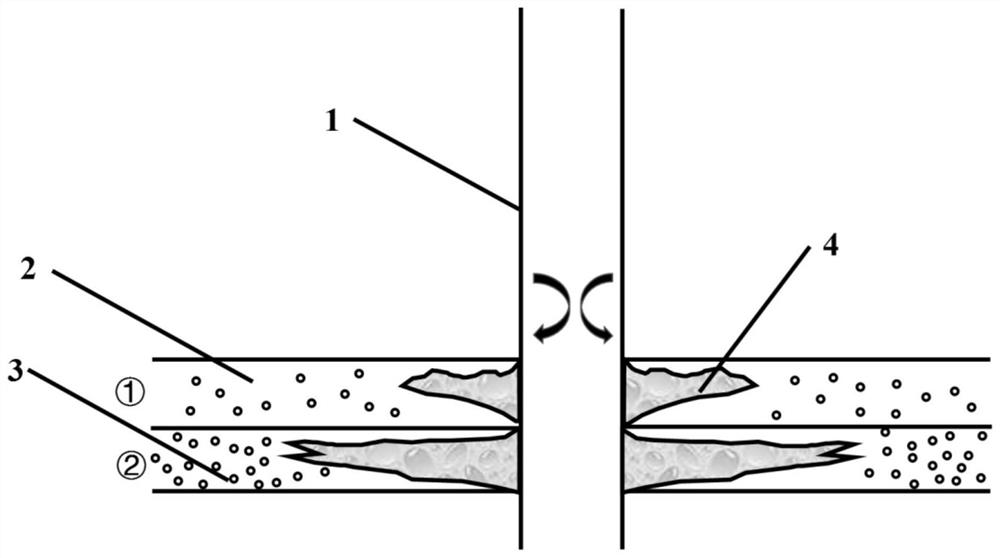
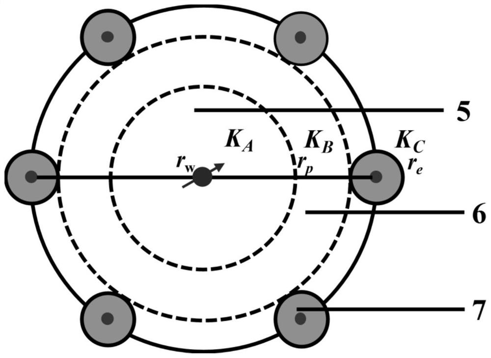
[0051] 2) Divide the specific interval into three areas, which are recorded as: area A where the biological nano-blocking deblocking agent is ...

Embodiment 2

[0063] Measure and calculate the radius of the bio-nano plug-removing fluid reaching the formation in multiple different layers, among which the 1839-1912m layer, r p =1.45m; 1939-2113m interval, r p =1.58m; 2181-2255m interval, r p = 1.72m; the reservoir thickness of each section is 18.8m, 24m, 28.9m, combined with the weighted average calculation of the reservoir thickness of each section, the average treatment radius of biological nano-blocking deblocking and increasing injection agent in the vertical direction is obtained:

[0064] combined formula (V is the amount of biological nano-blocking deblocking booster, m 3 ;r p is the radius of bio-nano-blocking deblocking booster injection agent reaching the formation, m; H is the thickness of the reservoir, m; is the average porosity of the reservoir, %), where H=71.7m, It can be calculated that the amount of biological nano-blocking deblocking and increasing injection agent is 116.4m 3 .

[0065] Combined with the ...


PUM


Abstract

The invention discloses a method for calculating the processing radius of a plug removal and augmented injection agent. The problem that the design processing radius of the unblocking and augmented injection agent is uncertain is solved. According to the technical scheme, an unstable seepage model of a specific layer section of a water injection well is combined with a water injection layer heat transfer model, and the relation between the water injection well water absorption profile and the temperature gradient is obtained; temperature and depth data obtained through well logging are substituted into the relation between the water absorption profile and the temperature gradient, data of the water absorption profile are obtained, and the water absorption difference of the specific interval can be obtained according to the data of the water absorption profile; and the processing radius of the plug removal and injection enhancement agent is calculated according to the water absorption difference. According to the method for calculating the processing radius of the plug removal and augmented injection agent, the calculation result is more reliable and better conforms to the field reality, the effect of improving the water injection profile of the water injection well can be improved, and finally the oil field recovery efficiency is improved.

Description

technical field [0001] This article involves but is not limited to the field of oil exploitation, and especially involves but is not limited to a calculation method for the treatment radius of plug-removing and injection-increasing agents. Background technique [0002] For offshore unconsolidated sandstone reservoirs, due to the poor cementation of reservoir rocks, problems such as particle migration, sand production and reservoir plugging are prone to occur during workover, profile control and water shutoff operations. Considering factors such as the limitation of offshore operating space and operating costs, hydraulic fracturing is generally not used for water injection wells in offshore oilfields, but acidification measures are often used to achieve plugging removal and injection enhancement. However, the treatment radius for plugging removal and injection increase is currently a difficult point. If the designed treatment radius of the agent is smaller than required, the ...

Claims


Application Information

Patent Timeline
Patent Type & Authority Applications(China)
IPC IPC(8): G06F30/20E21B37/06E21B43/27
CPCG06F30/20E21B37/06E21B43/27G06F2119/08
Inventor 冯青李啸南李胜胜杨慰兴黄子俊宫汝祥李敬松曾鸣樊爱彬杨浩高杰
Owner CHINA OILFIELD SERVICES
Why Eureka
Try Eureka