Tight coupling array antenna loaded with current loop and antenna unit

A technology of tightly coupled arrays and antenna units, which is applied in the direction of separately powered antenna arrays, antennas, antenna arrays, etc., can solve the problem of large size of array antennas, and achieve the effects of eliminating emission, enhancing radiation capabilities, and enhancing low-frequency radiation capabilities

Pending Publication Date: 2021-11-19
NORTHWEST INST OF NUCLEAR TECH
View PDF6 Cites 0 Cited by
  • Summary
  • Abstract
  • Description
  • Claims
  • Application Information

AI Technical Summary

Problems solved by technology

[0004] In order to solve the problem that the size of the array antenna used by the existing ultra-wideband array antenna is relatively large in order to effectively radiate the low-frequency component of the pulse, the present invention proposes a tightly coupled array antenna for loading a current loop, and also provides a antenna unit

Method used


Image

  • Tight coupling array antenna loaded with current loop and antenna unit
  • Tight coupling array antenna loaded with current loop and antenna unit
  • Tight coupling array antenna loaded with current loop and antenna unit

Examples


Embodiment Construction

[0037] The technical solutions of the present invention will be clearly and completely described below in conjunction with the accompanying drawings. Apparently, the described embodiments are some of the embodiments of the present invention, but not all of them. Based on the embodiments of the invention, all other embodiments obtained by persons of ordinary skill in the art without making creative efforts belong to the scope of protection of the present invention.

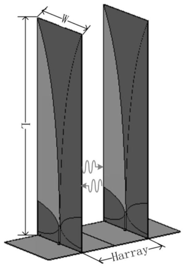
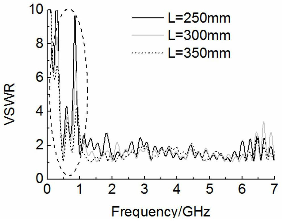
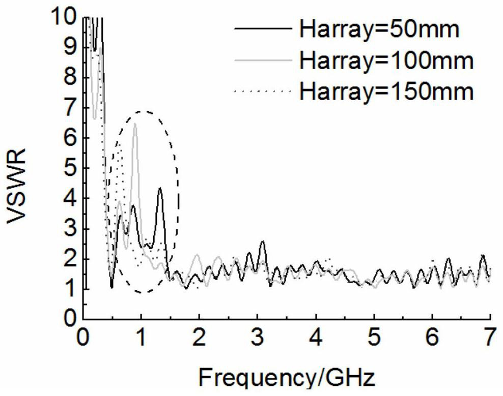
[0038] The existing array antenna structure such as figure 1 As shown, there is a resonance point in its VSWR. After simulation analysis, as shown in Figure 2(a,) 2(b) and 2(c), the frequency of the resonance point has little correlation with the length L of the antenna unit, but has little correlation with the antenna unit length L. The array spacing Harray of the elements in the H-plane direction has a large correlation with the antenna width W, that is, the current reaches the edge of the antenna element, and pa...


PUM


Abstract

The invention discloses a tight coupling array antenna loaded with a current loop and an antenna unit. The array antenna comprises a plurality of antenna units arranged according to an array, a tight coupling mechanism is formed between E surfaces of every two adjacent antenna units, and what is ensured is that the current amplitude of the two adjacent antenna units tends to be constant and the phase tends to be smoothly and gradually changed, equivalently, the electrical length of the unit is expanded by means of an adjacent unit structure; the array antenna has a good matching characteristic in a low frequency band, low frequency radiation with a small size is realized, the radiation main body part of each antenna unit is connected with the floor through the grounding strip, so that a current loop is formed, the current loop utilizes current which is not radiated out through an oral surface to form a magnetic vibrator, the magnetic vibrator and an electric vibrator of the antenna itself formcomplementarity, and therefore, emission can be eliminated, and the radiation capability can be further enhanced.

Description

technical field [0001] The invention relates to an ultra-wide-spectrum pulse radiation antenna, in particular to a tightly coupled array antenna and an antenna unit loaded with a current loop. Background technique [0002] Ultra-broadband electromagnetic pulses usually refer to pulse fronts or pulse widths in sub-nanoseconds (10 -10 s) magnitude, and the transient electromagnetic pulse in the range of tens of MHz to several GHz, has been widely used in many fields such as target detection, target recognition, electromagnetic compatibility, and biomedicine. The ultra-broadband array antenna is the core component of the ultra-broadband electromagnetic pulse system, and its function is to radiate the ultra-broadband pulse generated by the pulse source to a designated area with a certain beam width. [0003] Miniaturization of UWB array antennas is a problem that must be solved for UWB EMP systems to be practically applied. Due to the rich frequency components of ultra-wideban...

Claims


Application Information

Patent Timeline
Patent Type & Authority Applications(China)
IPC IPC(8): H01Q21/06H01Q1/48H01Q1/36H01Q1/50
CPCH01Q21/061H01Q1/48H01Q1/36H01Q1/50
Inventor 谢佳玲乔汉青易超龙方旭石一平樊亚军夏文锋朱郁丰石磊卢彦雷张兴家王翔宇刘启晨张冬晓蒋灯陈昌华
Owner NORTHWEST INST OF NUCLEAR TECH
Why Eureka
Try Eureka