Pouring system and method for producing rollers

A pouring system and pouring method technology, applied in the field of compressors, can solve problems such as uneven hardness of rollers, excessive thermal expansion coefficient, etc., and achieve the effects of low connection strength, improved yield, and improved purity

Pending Publication Date: 2021-11-23
芜湖格力精密制造有限公司 +1
View PDF0 Cites 0 Cited by
  • Summary
  • Abstract
  • Description
  • Claims
  • Application Information

AI Technical Summary

Problems solved by technology

[0007] The purpose of the present invention is to propose a gating system and method for producing rollers, which solves the technical pro...

Method used


Image

  • Pouring system and method for producing rollers
  • Pouring system and method for producing rollers
  • Pouring system and method for producing rollers

Examples


Embodiment 1

[0037] This embodiment describes in detail the pouring system used for producing rollers of the present invention.

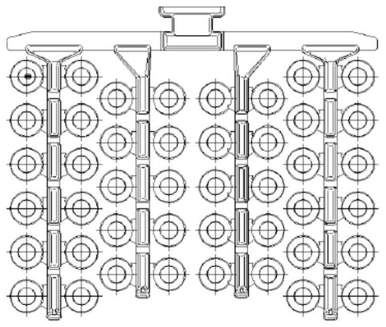
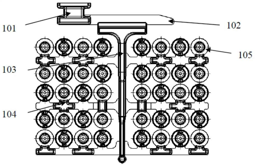
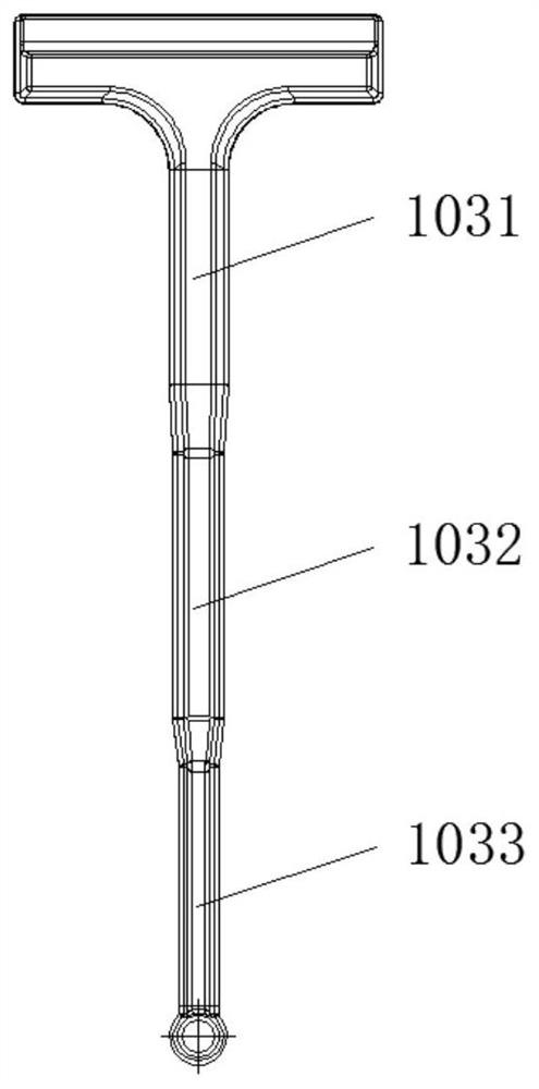
[0038] This embodiment is used for the gating system of producing roller, comprises sprue cup 101, runner 102, sprue 103, a plurality of inrunners 104 and a plurality of roller molds 105, as figure 2 shown. Preferably, the sprue cup 101 is communicated with the runner 102, the sprue 103 is communicated with the runner 102, a plurality of inrunners 104 are distributed on the side of the sprue 103 and communicated with the sprue 103, and the plurality of runners The sub-mold 105 is distributed on the upper side and / or the lower side of the inner runner 104 and communicates with the inner runner 104, such as figure 2 shown. More preferably, the cross-sectional area of ​​the sprue 103 gradually decreases from one end close to the sprue 102 to an end far away from the sprue 102, and the inner sprue 104 connected to different positions of the sprue 103 is simultan...

Embodiment 2

[0047] This embodiment describes in detail the pouring method for producing rollers of the present invention.

[0048] The pouring method that this embodiment is used for producing roller is to utilize any technical scheme in embodiment 1 to be used for the pouring system of producing roller to finish. Preferably, the pouring method used to produce the roller in this embodiment includes the following steps:

[0049] S1: pour molten iron into the sprue cup 101 .

[0050] S2: The molten iron in the sprue cup 101 flows into the sprue 103 through the runner 102 .

[0051] S3: The molten iron in the sprue 103 is distributed to the ingate 104.

[0052] S4: The molten iron in the runner 104 flows into the roller mold 105, and the runner 104 near the end of the runner 102 and the runner 104 at the end far away from the runner 102 complete the filling of the roller mold 105 at the same time .

[0053] The pouring method used in this embodiment to produce rollers is realized by util...


PUM

PropertyMeasurementUnit
Cross-sectional areaaaaaaaaaaa
Widthaaaaaaaaaa

Abstract

The invention discloses a pouring system and method for producing rollers, and relates to the technical field of compressors. The problems that rollers produced by a pouring system for producing rollers in the prior art are non-uniform in hardness and the coefficient of thermal expansion exceeds the standard are solved. A pouring cup of the pouring system communicates with a transverse pouring gate, a straight pouring gate communicates with the transverse pouring gate, a plurality of inner pouring gates are distributed on the side face of the straight pouring gate and communicate with the straight pouring gate, and a plurality of roller molds are distributed on the upper sides and/or the lower sides of the inner pouring gates and communicate with the inner pouring gates. The cross sectional area of the straight pouring gate is gradually reduced from one end close to the transverse pouring gate to one end far away from the transverse pouring gate, and the inner pouring gates connected to different positions of the straight pouring gate simultaneously complete mold filling of the roller molds. According to the pouring system, the rollers at different positions can be cooled simultaneously, the cooling temperature difference of the rollers is reduced, the difference of crystal structures in the rollers at different positions is reduced, the hardness consistency of the rollers at different positions is ensured, and the thermal expansion coefficient of the rollers at different positions is reduced.

Description

technical field [0001] The invention relates to the technical field of compressors, in particular to a casting system for producing rollers and a casting method for producing rollers using the casting system. Background technique [0002] With the increasing application of rolling rotor compressors, people's demand for air conditioners continues to increase, especially the gradual expansion of the export field, and the conditions for air conditioners to be used in high heat, high humidity, extreme cold and other environments are becoming more and more severe. This makes the requirements for the working environment of the rolling rotor compressor more stringent, especially for the performance of the key components inside the compressor. [0003] The small size of the roller, but the high-speed rotation and grinding it bears play a decisive role in the stability of the rolling rotor compressor, the ultra-quiet effect and the service life of the compressor. Especially in the h...

Claims


Application Information

Patent Timeline
IPC IPC(8): B22C9/08B22C9/20B22C9/28
CPCB22C9/082B22C9/20B22C9/28B22C9/088
Inventor 许勇林志华苏江涛李三宣郭海石金林
Owner 芜湖格力精密制造有限公司
Why Eureka
Try Eureka