EGR rate control method and device

A control method and EGR valve technology, applied in electrical control, engine control, fuel injection control, etc., can solve the problem of inability to meet the requirements of engine working conditions, inability to truly reflect EGR rate, low accuracy of exhaust gas volume and fresh air volume control and other problems, to achieve the effect of ensuring control accuracy, improving combustion phase, and realizing dynamic control

Active Publication Date: 2021-11-23
GUANGZHOU AUTOMOBILE GROUP CO LTD
View PDF7 Cites 0 Cited by
  • Summary
  • Abstract
  • Description
  • Claims
  • Application Information

AI Technical Summary

Problems solved by technology

However, it has been found in practice that since the intake amount of exhaust gas is controlled by the EGR valve, and there is a long pipeline between the EGR valve and the engine cylinder, it takes a certain time for the exhaust gas to enter the engine cylinder, which can easil

Method used


Image

  • EGR rate control method and device
  • EGR rate control method and device
  • EGR rate control method and device

Examples


Example Embodiment

[0033] Example one

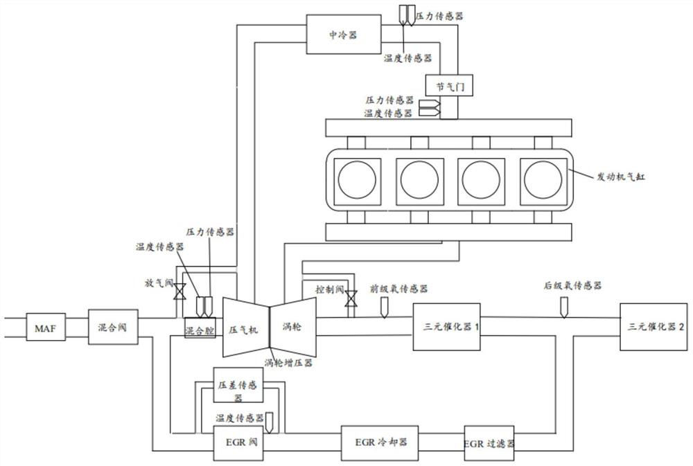
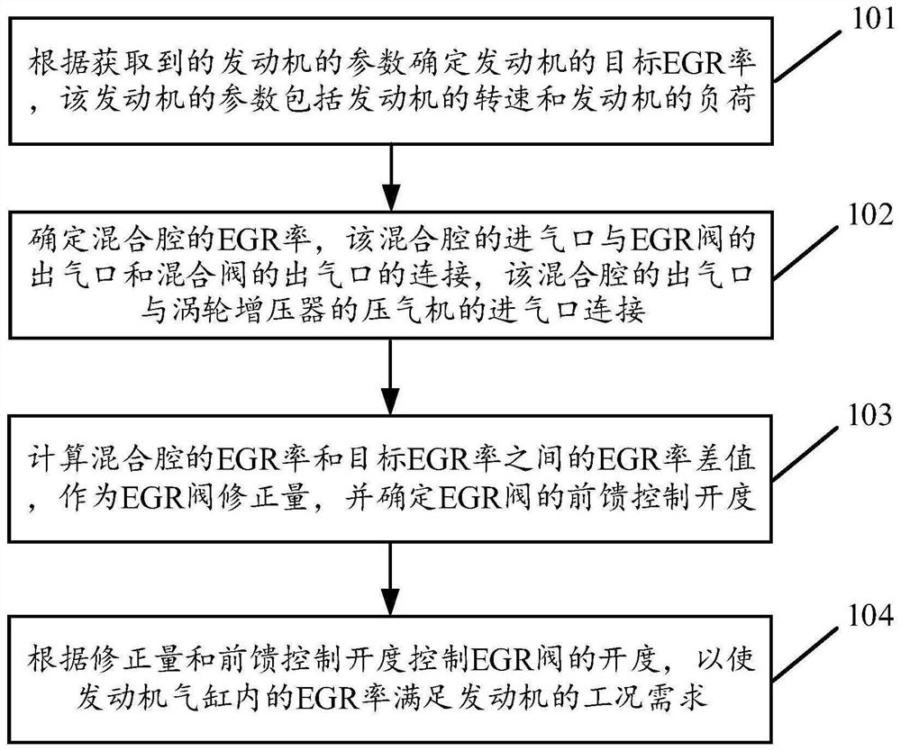
[0034] See figure 2 , figure 2 It is a flow chart of a control method of an EGR ratio disclosed in the embodiment of the present invention. in, figure 2 The control method of the described EGR rate is applicable to figure 1 The described engine system is described. like figure 2 As shown, the control method of the EGR rate can include the following operations:

[0035] 101. Determine the target EGR ratio of the engine based on the parameter of the acquired engine, the engine's parameters including the engine speed and the load of the engine.

[0036] In the embodiment of the present invention, the engine comprises any one of a gasoline engine or a diesel engine, and an embodiment of the present invention is not limited.

[0037] In the embodiment of the present invention, an EGR rate table is established in advance, which includes different engine speed and EGR ratio corresponding to the load of different engines, and different engines rotation and different e...

Example Embodiment

[0122] Example 2

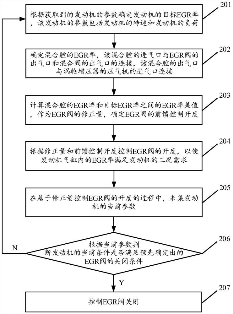
[0123] See image 3 , image 3 It is a flow diagram of another method of controlling the EGR rate according to the disclosed embodiment of the present invention. in, image 3 The method of controlling the EGR rate as described herein are applicable to figure 1 The engine system as described herein. like image 3 Shown, the EGR rate control method may include the following operations:

[0124] 201, determines a target EGR rate of the engine based on the parameter acquired engine parameters including engine speed and an engine load of the engine.

[0125] 202, it is determined the EGR rate of the mixing chamber, the compressor outlet connected to the inlet and outlet of the mixing chamber of the EGR valve and the mixing valve, the outlet of the mixing chamber with a turbocharger connected to the intake port.

[0126] 203, the difference between the calculated EGR rate EGR rate and the mixing chamber of the target EGR rate, the EGR valve as the correction amount.

[01...

Example Embodiment

[0143] Example three

[0144] See Figure 4 , Figure 4 It is a control device for an EGR rate disclosed in the embodiment of the present invention. Figure 4 The described EGR control is applied to figure 1 The described engine system is described. like Figure 4 As shown, the EGR control device can include:

[0145] Memory 401 stored in executable program code;

[0146] Processor 402 coupled to memory 401;

[0147] Further, it is also possible to include an input interface 403 and an output interface 404 coupled to the processor 402;

[0148] The processor 402 calls the executable program code stored in the memory 401 to perform the step of performing the control method of the EGR ratio described in the first embodiment or the second embodiment.


PUM


Abstract

The invention discloses an EGR rate control method and device. The method comprises the steps that the target EGR rate of an engine is determined according to the obtained parameters of the engine, and the EGR rate of a mixing cavity is determined; the EGR rate difference value between the EGR rate of the mixing cavity and a target EGR rate is calculated, and the feedforward control opening degree of an EGR valve is determined; and the opening degree of the EGR valve is controlled according to the correction amount and the feedforward control opening degree, so that the EGR rate in an engine air cylinder meets the working condition requirement of the engine, closed-loop control is conducted on the EGR rate of the engine air cylinder, and dynamic control over the EGR rate is achieved. According to the EGR rate control method and device, it can be seen that according to the EGR rate difference value between the EGR rate of the mixing cavity and the target EGR rate of the engine, the opening degree of the EGR valve is corrected according to the EGR rate difference value, the control accuracy of the amount of waste gas and the amount of fresh air entering the air cylinder in each cycle can be improved, and therefore the EGR rate in the air cylinder meets the working condition requirement of the engine; and closed-loop control is carried out on the EGR rate of the engine air cylinder, so that dynamic control of the EGR rate is realized.

Description

Technical field [0001] The present invention relates to an engine control technology, and particularly to a method and apparatus for controlling the EGR rate. Background technique [0002] A low-pressure exhaust gas recirculation technique (Low Pressure Exhaust Gas Re-circulation, LP-EGR) is the energy saving engine hot technology, the principle is the engine exhaust gases back to the combustion engine's intake system, and together with the fresh air participate in the combustion of fuel in the cylinder. Since the exhaust gases of the engine combustion contains a large specific heat capacity larger carbon dioxide, water, etc. triatomic molecules, therefore, when the exhaust gas is returned to the engine cylinder, the triatomic molecules in the exhaust gas can be charge within the cylinder dilution, improving fuel phase combustion, combustion gas temperature can be reduced in the cylinder combustion chamber, the combustion chamber and further combustion of the fuel, helps to reduc...

Claims


Application Information

Patent Timeline
IPC IPC(8): F02D41/00F02M26/06F02M26/19F02M26/20
CPCF02D41/0077F02D41/0072F02D41/0052F02M26/06F02M26/20F02M26/19
Inventor 施信信何宇连学通吴中浪徐广兰赵伟博
Owner GUANGZHOU AUTOMOBILE GROUP CO LTD
Why Eureka
Try Eureka