Sludge carbonization device for environmental protection equipment

A technology of carbonization device and environmental protection equipment, applied in sludge treatment, pyrolysis treatment of sludge, water/sludge/sewage treatment, etc. Precise quantitative effect

Pending Publication Date: 2021-11-26
胡太为
View PDF0 Cites 0 Cited by
  • Summary
  • Abstract
  • Description
  • Claims
  • Application Information

AI Technical Summary

Problems solved by technology

[0002] The so-called sludge carbonization is the process of heating and pressurizing the sludge in time to crack the cells in the biochemical sludge, release the water in it, and at the same time retain the carbon in the sludge to the greatest extent. The process of sludge carbonization The advantage is that sludge carbonization removes the water in the sludge by cracking, with less energy consumption, high carbon content in the remaining products, and high calorific value, and most of the water in the sludge is removed by heating and evaporation. High energy consumption, low carbon content in ash, low utilization value
[0003] The existing sludge carbonization treatment is carried out in batches. The sludge is dehydrated first, and then the dehydrated sludge is put into quantitative batches for quantitative batch treatment. However, since the dehydrated sludge is mostly semi-solid residue , the residues are different in softness and hardness, and there are gaps of different sizes between the residues, which makes it difficult to guarantee the quantitative accuracy, and the cumulative error becomes larger, resulting in inaccurate sludge volume after entering the drying furnace and gasification furnace, which affects the subsequent sludge moisture content. The treatment has a certain impact, for this reason, we propose a sludge carbonization device for environmental protection equipment

Method used


Image

  • Sludge carbonization device for environmental protection equipment
  • Sludge carbonization device for environmental protection equipment
  • Sludge carbonization device for environmental protection equipment

Examples


Embodiment 1

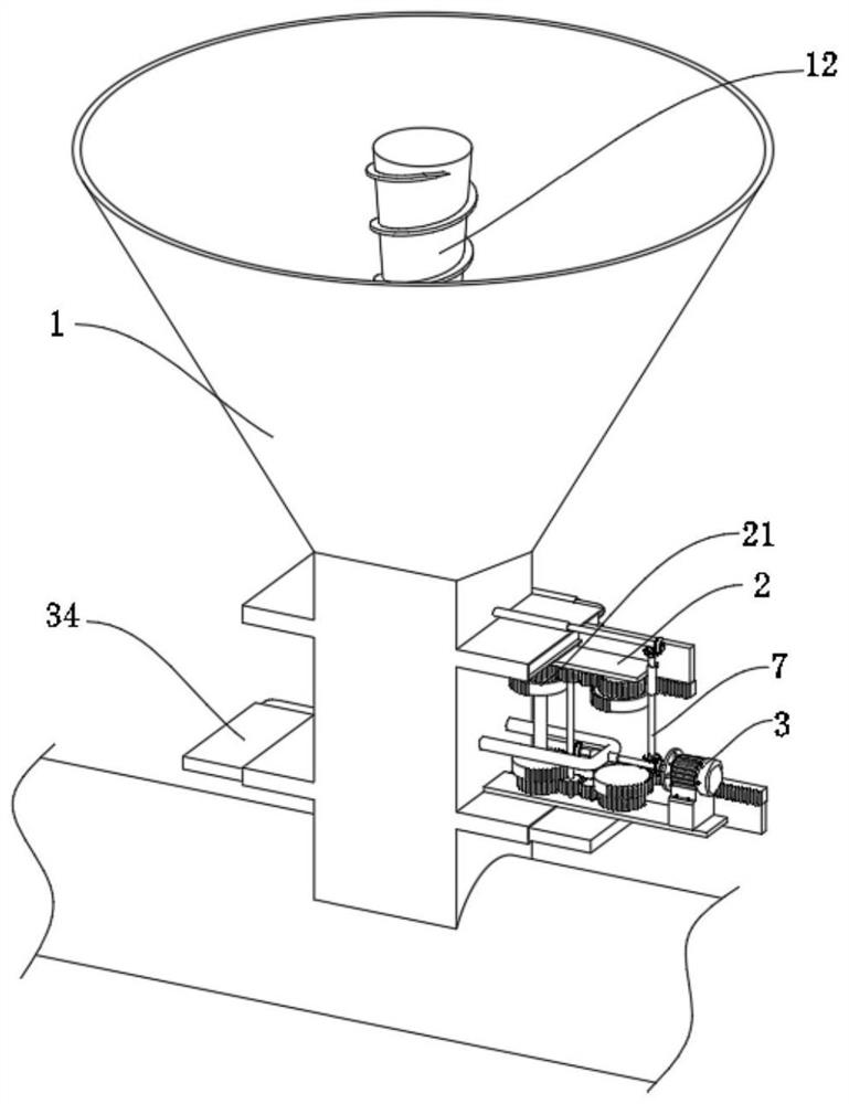
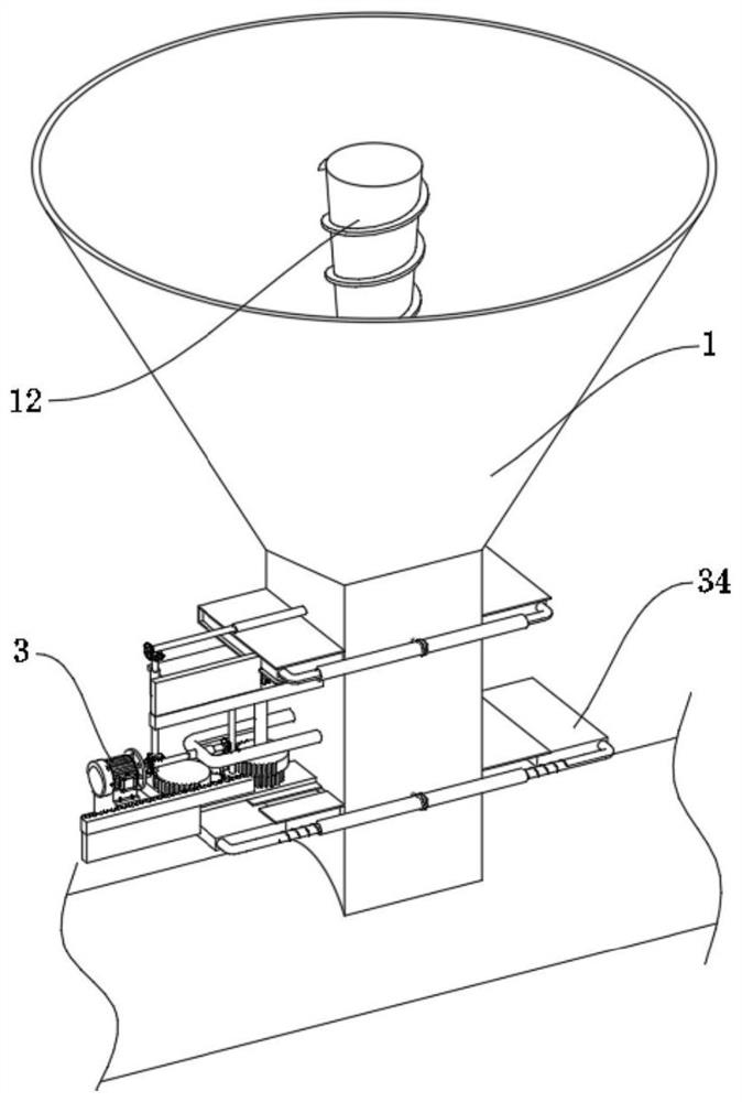
[0032] see Figure 1-6 , 9-10, a sludge carbonization device for environmental protection equipment in the illustration, including: a feeding cylinder 1 communicated and fixed with a connecting pipeline; it is characterized in that: it also includes two fixed plates 2 distributed in a symmetrical structure , the fixed plate 2 is connected and fixed with the feeding cylinder 1, and the outer side of the fixed plate 2 is provided with a blocking assembly 34;

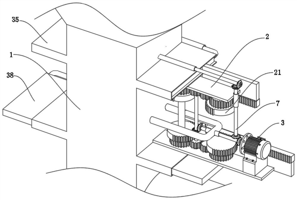
[0033] A motor 3, the output shaft of the motor 3 is fixedly connected with a third rotating rod 4, one end of the third rotating rod 4 is fixedly connected with the sixth bevel gear 5, and the other end of the third rotating rod 4 is fixedly connected with the seventh cone Gear 6, one side of the seventh bevel gear 6 is provided with an adjustment assembly 21 for adjusting the opening and closing of the blocking assembly 34;

[0034] The linkage assembly 7 is used to connect the blocking assembly 34 and the adjustment as...

Embodiment 2

[0042] Reference attached Figure 8 Embodiment 2 is illustrated. This embodiment is further described with respect to Embodiment 1. A protective layer is stuck on the inside of the two movable panels 38 located in the horizontal position. When the movable panels 38 are close to each other, rigidity will appear in the two movable panels 38. Collision, through the protective layer, avoids deformation of structures such as the limit frame 35 and increases the durability of the equipment.

[0043] In order to avoid leakage when the movable plates 38 are closed and opened, the drum 8 is located between two movable plates 38 distributed up and down, and the diameter of the movable plates 38 is adapted to the width of the movable plates 38 .

Embodiment 3

[0045] Reference attached Figure 7 Embodiment 3 is described. This embodiment is further described relative to Embodiment 1. The stirring rod 12 has a structure with a wide top and a narrow bottom, and the roll plate 13 has a downward-sloping structure as a whole.

[0046] Through the rotation of the stirring rod 12 with a wide top and narrow bottom structure and the rolling plate 13 with a downward sloping structure, an inclined downward rotational pressure is given to the sludge in the feeding barrel 1, which facilitates the dewatered sludge to move downward. Entering the drum 8, on the one hand, it crushes and squeezes the sludge with different softness and hardness, and on the other hand, it continuously pushes the sludge into the drum 8 to ensure that the drum 8 is filled with sludge, so that the sludge is quantified accurately.


PUM


Abstract

The invention discloses a sludge carbonization device for environmental protection equipment. The sludge carbonization device comprises a feeding cylinder; two fixing plates, which are distributed in a symmetrical structure and are fixedly connected with the feeding cylinder, wherein plugging assemblies are arranged on the outer sides of the fixing plates; a motor, wherein an output shaft of the motor is fixedly connected with a third rotating rod, one end of the third rotating rod is fixedly connected with a sixth bevel gear, the other end of the third rotating rod is fixedly connected with a seventh bevel gear, and one side of the seventh bevel gear is provided with an adjusting assembly used for adjusting opening and closing of the plugging assemblies; and a linkage assembly, which is used for being connected between the plugging assemblies and the adjusting assembly. Through rotation of the motor, closing and opening of an upper movable plate and closing and opening of a lower movable plate are matched with each other, and drum rotating, sludge blocking quantification and sludge opening after quantification are completed.

Description

technical field [0001] The invention relates to the technical field of sludge carbonization equipment, in particular to a sludge carbonization device used in environmental protection equipment. Background technique [0002] The so-called sludge carbonization is the process of heating and pressurizing the sludge in time to crack the cells in the biochemical sludge, release the water in it, and at the same time retain the carbon in the sludge to the greatest extent. The process of sludge carbonization The advantage is that sludge carbonization removes the water in the sludge by cracking, with less energy consumption, high carbon content in the remaining products, and high calorific value, and most of the water in the sludge is removed by heating and evaporation. High energy consumption, low carbon content in ash, and low utilization value. [0003] The existing sludge carbonization treatment is carried out in batches. The sludge is dehydrated first, and then the dehydrated sl...

Claims


Application Information

Patent Timeline
Patent Type & Authority Applications(China)
IPC IPC(8): C02F11/10C02F11/121B01F7/24B01F15/00B01F15/02
Inventor 不公告发明人
Owner 胡太为
Why Eureka
Try Eureka