Fly ball assembly part of single-cylinder diesel engine
A technology for assembly components and diesel engines, which is applied in the direction of engine components, mechanical equipment, engine control, etc., can solve the problems of difficult control of dynamic balance indicators, increased vibration of diesel engines, and large centrifugal force, so as to improve the stability and accuracy of power output The effect of controlling performance, optimizing fuel consumption and
- Summary
- Abstract
- Description
- Claims
- Application Information
AI Technical Summary
Problems solved by technology
Method used
Image
Examples
Embodiment 1
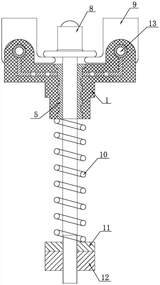
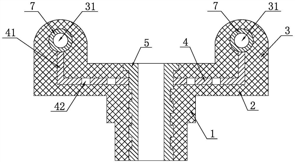
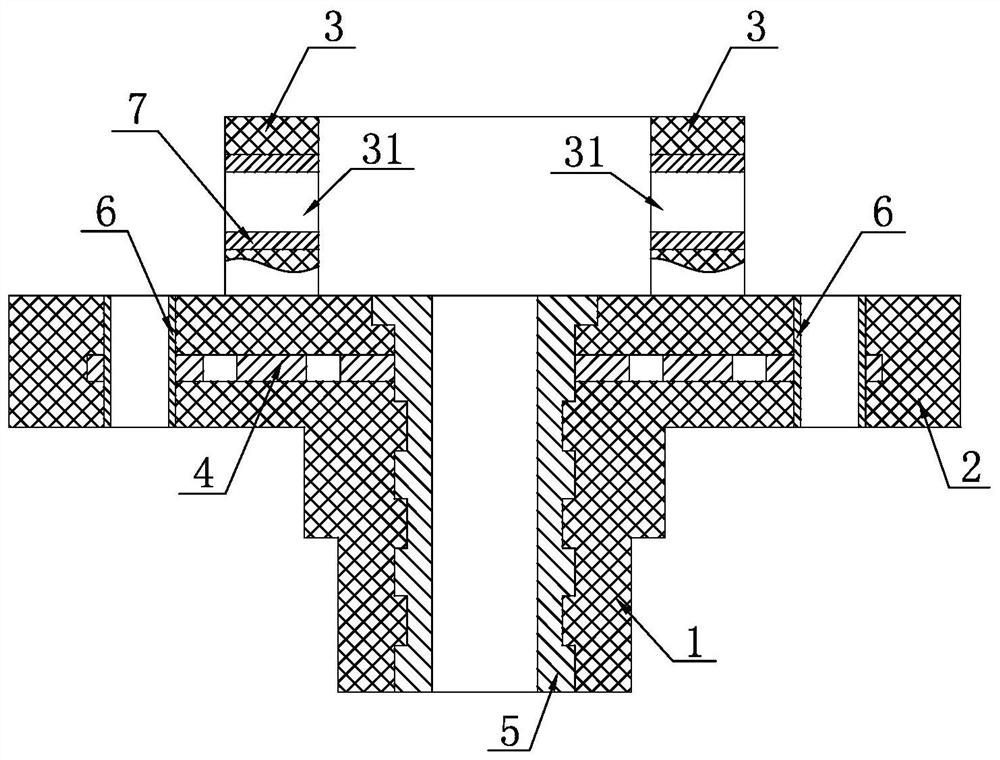
[0026] Embodiment 1: A single-cylinder diesel engine flyweight assembly, as shown in the figure, includes a flyweight connecting seat, a mandrel rod part 8, a flyweight block 9, a compression spring 10, a lower spring seat 11, an adjusting nut 12 and The pin shaft 13 and the mandrel rod part 8 are steel ball 81, steel ball placement section 82, execution shoulder 83, matching section 84, connection section 85 and thread section 86 from top to bottom. Steel ball 81 is installed on the steel ball placement section. On the upper end surface of the section 82, the executive shoulder 83 is arranged between the steel ball placement section 82 and the matching section 84, the matching section 84 is set in the center bushing 5, and the compression spring 10 is set on the connecting section 85 and the threaded section 86, The upper and lower ends of the compression spring 10 are respectively in contact with the lower end surface of the flyweight connecting seat and the upper end surface...
Embodiment 2
[0027] Embodiment 2: On the basis of Embodiment 1, an upward flanging body 41 is provided on the metal inlaid plate 4 corresponding to the non-metallic connecting ear group 3, and the flanging body 41 is embedded in the non-metallic connecting ear group 3, The non-metallic connecting ear group 3 is fixedly connected with the non-metallic seat plate 2 as a whole.
Embodiment 3
[0028] Embodiment 3: On the basis of Embodiment 1, a pin sleeve 7 is inlaid in the pin hole 31 of the non-metallic connecting ear group 3, and an upward flange is provided on the corresponding position of the pin sleeve 7 and the metal inlaid plate 4 Body 41 is welded into one.
PUM
 Abstract
Description
Claims
Application Information
 - R&D
- Intellectual Property
- Life Sciences
- Materials
- Tech Scout
- Unparalleled Data Quality
- Higher Quality Content
- 60% Fewer Hallucinations
Browse by: Latest US Patents, China's latest patents, Technical Efficacy Thesaurus, Application Domain, Technology Topic, Popular Technical Reports.
© 2025 PatSnap. All rights reserved.Legal|Privacy policy|Modern Slavery Act Transparency Statement|Sitemap|About US| Contact US: help@patsnap.com


