Temperature-pressure coupling bidirectional electromagnetic loading dynamic compression-shear experimental device and testing method

A technology of experimental device and temperature measuring device, which is applied in the direction of testing material strength by applying stable shear force, testing material strength by applying stable tension/compression, measuring devices, etc.

Inactive Publication Date: 2021-11-26
SHENZHEN UNIV
View PDF19 Cites 7 Cited by
  • Summary
  • Abstract
  • Description
  • Claims
  • Application Information

AI Technical Summary

Problems solved by technology

[0005] In view of the above-mentioned deficiencies in the prior art, the purpose of the present invention is to provide a temperature-pressure coupling bidirectional electromagnetic loading dynamic c...

Method used


Image

  • Temperature-pressure coupling bidirectional electromagnetic loading dynamic compression-shear experimental device and testing method
  • Temperature-pressure coupling bidirectional electromagnetic loading dynamic compression-shear experimental device and testing method
  • Temperature-pressure coupling bidirectional electromagnetic loading dynamic compression-shear experimental device and testing method

Examples


Embodiment 1

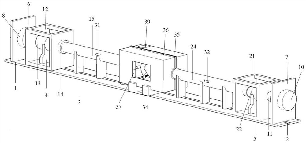
[0055] Place the left servo-controlled loading cylinder support base 6, the left loading frame 12, the loading rod support base 3, the right loading frame 21 and the right servo-controlled loading cylinder support base 7 from left to right on the support platform in sequence according to actual needs 1, the left servo control loading cylinder 8 is fixed on the left servo control loading cylinder support base 6, the right end surface of the left piston rod 9 is freely attached to the left end surface of the left loading frame 12, and the left electromagnetic pulse generator 13 Place it on the support base 4 of the left electromagnetic pulse generator, place the left electromagnetic pulse generator support base 4 and the left electromagnetic pulse generator 13 in the left loading frame 12, put the TC21 titanium alloy with a length of 2000 mm and a diameter of 50 mm on the left side The loading rod 15 is placed on the loading rod support base 3, the left loading rod 15 is parallel...

Embodiment 2

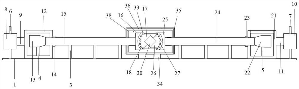
[0061] Place the left servo-controlled loading cylinder support base 6, the left loading frame 12, the loading rod support base 3, the right loading frame 21 and the right servo-controlled loading cylinder support base 7 from left to right on the support platform in sequence according to actual needs 1, the left servo control loading cylinder 8 is fixed on the left servo control loading cylinder support base 6, the right end surface of the left piston rod 9 is fixed on the left end surface of the left loading frame 12, and the left electromagnetic pulse generator 13 is placed on On the left electromagnetic pulse generator support base 4, the left electromagnetic pulse generator support base 4 and the left electromagnetic pulse generator 13 are placed in the left loading frame 12, and a TC21 titanium alloy left loading rod with a length of 2000 mm and a diameter of 50 mm is placed 15 is placed on the supporting base 3 of the loading rod, the loading rod is parallel to the axis d...

Embodiment 3

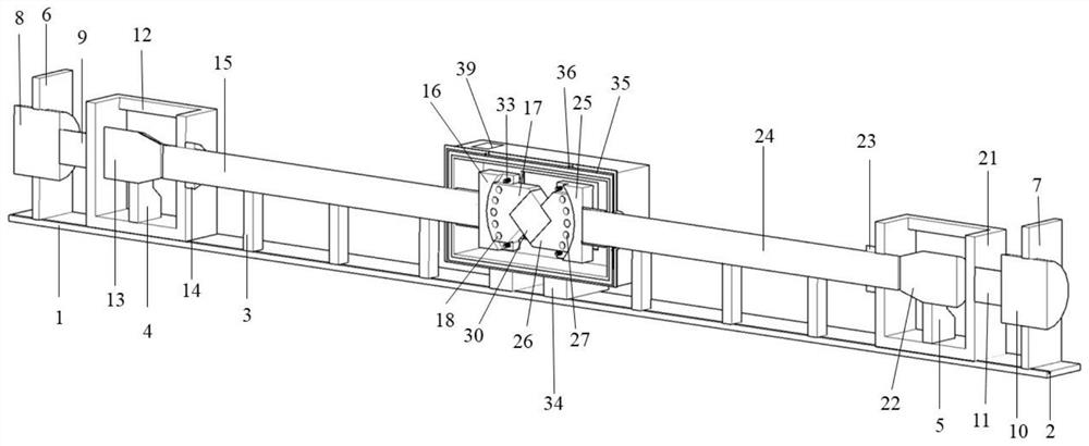
[0073] Such as Figure 7 As shown, place the left servo-controlled loading cylinder support base 6, the left loading frame 12, the loading rod support base 3, the right loading frame 21 and the right servo-controlled loading cylinder support base 7 from left to right according to actual needs. On the support platform 1, the left servo-controlled loading cylinder 8 is fixed on the left servo-controlled loading cylinder support base 6, the right end surface of the left piston rod 9 is freely attached to the left end surface of the left loading frame 12, and the left electromagnetic pulse The generator 13 is placed on the left electromagnetic pulse generator support base 4, the left electromagnetic pulse generator support base 4 and the left electromagnetic pulse generator 13 are placed in the left loading frame 12, and the TC21 titanium with a length of 3000 mm and a diameter of 75 mm The alloy left loading rod 15 is placed on the loading rod support base 3, the left loading rod...


PUM


Abstract

The invention discloses a temperature-pressure coupling bidirectional electromagnetic loading dynamic compression-shear experimental device and a testing method. The device comprises a supporting seat, a loading rod, a dynamic loading device, a static loading device, a temperature control mechanism and a dynamic compression-shear mold arranged in the temperature control mechanism. By arranging the temperature control mechanism, the device can perform temperature rise and heat preservation on the test sample before and in the dynamic and static combined compression-shear test, so that dynamic and static combined compression-shear test research on the test sample under the condition of temperature-pressure coupling is realized. The problem that in the prior art, dynamic compression-shear tests of rock-like solid materials such as rocks and concrete under different temperature and static prestress environment conditions cannot be carried out is solved, so that test conditions are closer to real occurrence and working conditions of the rock-like solid materials such as rocks and concrete under a natural environment; therefore, a test result can be closer to a real situation, and the device and method have more scientific value and practical significance for engineering practice.

Description

technical field [0001] The invention relates to the technical field of dynamic compression-shear testing of solid materials such as rocks and concrete, and in particular to a dynamic compression-shear experimental device and a testing method for temperature-pressure coupled bidirectional electromagnetic loading. Background technique [0002] With the increasing demand for the development and utilization of energy resources and transportation, more and more deep rock engineering (deep mining, tunnels, water conservancy, geothermal development, and nuclear waste storage, etc.) The construction of areas with active disturbance causes the underground rock mass in these areas not only to bear the effect of axial static stress, but also often affected by dynamic loads such as earthquakes, explosions, and engineering disturbances; in addition, deep rock mass engineering is also accompanied by high ground temperature. Especially in the development and utilization of deep hot dry roc...

Claims


Application Information

Patent Timeline
IPC IPC(8): G01N3/18G01N3/24G01N3/02
CPCG01N3/18G01N3/24G01N3/02G01N2203/0019G01N2203/0025G01N2203/0226
Inventor 周韬殷雪菡朱建波谢和平
Owner SHENZHEN UNIV
Why Eureka
Try Eureka