Coil of wireless power transmission system and winding method thereof

A technology of wireless energy transmission and winding method, which is applied in the direction of coil manufacturing, transformer/inductor coil/winding/connection, transformer/inductor parts, etc., which can solve the problems of coil AC internal resistance increase and uneven current density, etc. , to achieve the effect of reducing the AC internal resistance and reducing the skin effect

Pending Publication Date: 2021-11-26
GUANGXI POWER GRID ELECTRIC POWER RES INST
0 Cites 0 Cited by

AI-Extracted Technical Summary

Problems solved by technology

[0006] The purpose of the present invention is to provide a coil of a wireless power transmission system and its winding method, which can so...

Method used

In order to reduce the high-frequency operating state, the influence of the proximity effect between the coils, and then reduce the AC internal resistance of the coil under the high-frequency operating state, the coil of the present invention adopts a spiral winding method, and each turn of the coil has formed a A portion of a hollow circular section arc. Each turn of the coil is evenly arranged on the circular circumference, so that the magnetic fields between the conductors cancel each other to reduce the influence of the proximity effect on the internal resistance of the coil, and reduce the AC internal resistance of the coil at high frequencies. Specifically, the mutual resistance effect of the magnetic field generated between each turn of the coil is shown in Figure 5. It can be seen that the coil adopts the space winding method in the present invention to make the current flow through the conductor more uniformly, which can effectively reduce the coil in the high-frequency working state. Reduce the loss caused by the proximity effect, thereby reducing the AC internal resistance of the coil at high frequencies. The coil of this special winding method is circular in any cross-section, and the n-turn coils are evenly distributed on this circumference. From ...

Abstract

The invention provides a coil of a wireless power transmission system and a winding method thereof. The coil comprises a carrier and a Litz wire wound on the carrier, and is characterized in that a plurality of circles of threaded limiting grooves parallel to the periphery of a hollow circular ring are uniformly formed in the outer surface of the hollow circular ring, the threaded limiting grooves are uniformly arranged on the peripheral surface of the carrier, and the Litz wire is wound along the threaded limiting grooves to form N turns of coils. According to the coil of the wireless electric energy transmission system and the winding method of the coil, the Litz wire is adopted for spiral winding, all turns of the coil are smoothly connected, each section of the coil in the space is in the shape of a hollow circle, the Litz wire is adopted for winding the coil, the influence of the skin effect of the coil in the high-frequency working state can be reduced, and the alternating-current internal resistance of the coil under high frequency is further reduced.

Application Domain

Technology Topic

Skin effectTransmission system +7

Image

  • Coil of wireless power transmission system and winding method thereof
  • Coil of wireless power transmission system and winding method thereof
  • Coil of wireless power transmission system and winding method thereof

Examples

  • Experimental program(1)

Example Embodiment

[0021] The embodiments of the present disclosure will be described in detail below with reference to the accompanying drawings.
[0022] The embodiments of the present disclosure are described below through specific specific examples, and those skilled in the art can easily understand other advantages and effects of the present disclosure from the contents disclosed in this specification. Obviously, the described embodiments are only some, but not all, embodiments of the present disclosure. The present disclosure can also be implemented or applied through other different specific embodiments, and various details in this specification can also be modified or changed based on different viewpoints and applications without departing from the spirit of the present disclosure. It should be noted that the following embodiments and features in the embodiments may be combined with each other under the condition of no conflict. Based on the embodiments in the present disclosure, all other embodiments obtained by those of ordinary skill in the art without creative efforts shall fall within the protection scope of the present disclosure.
[0023] A coil of a wireless power transmission system of the present invention includes a carrier and a Litz wire wound on the carrier, the carrier is a hollow ring formed by 3D printing, and the outer surface of the hollow ring is uniformly provided with several circles and the outer circumference of the hollow ring Parallel thread limit grooves, the thread limit grooves are evenly arranged on the outer surface of the carrier, and the Litz wire is wound along the thread limit groove to form a coil. Space between adjacent thread limit grooves where N is the number of thread turns.
[0024] A coil winding method for a wireless power transmission system of the present invention includes the following steps: using a hollow ring as a carrier, the outer surface of the hollow ring is evenly provided with a number of thread limit grooves parallel to the outer circumference of the hollow ring, The Litz wire starts from the starting end of the first circle of limit slots and wraps along the outer circumference of the ring to the end of the first circle of limit slots to form the first coil, and the end of the first circle of limit slots is the second circle of limit slots. Continue to wrap around the outer circumference of the ring from the starting end of the limit slot of the second circle to the end of the limit slot of the second circle to form the second coil, and the end of the limit slot of the second circle is the third circle The start end of the limit slot; and so on until the end of the limit slot of the Nth circle is connected to the start end of the limit slot of the first circle to form the Nth turn of the coil.
[0025] The interval between two adjacent turns of the coil
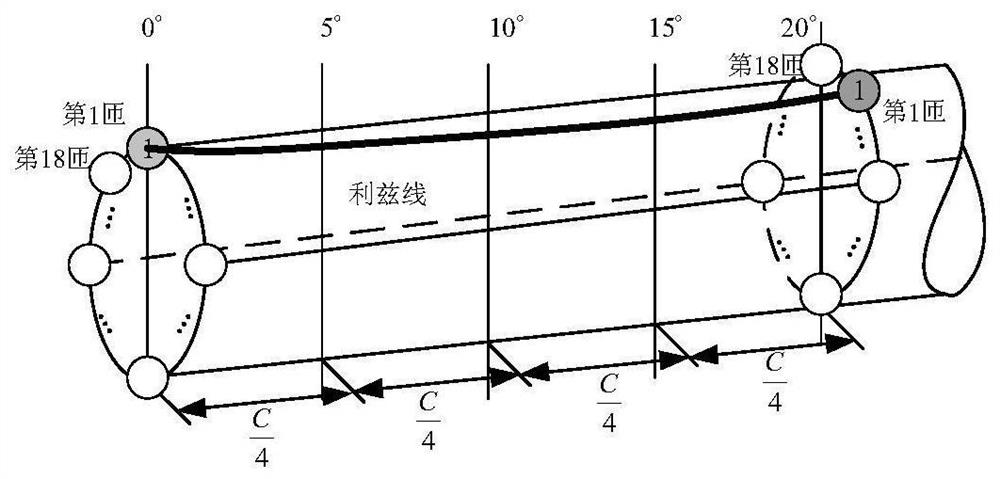
[0026] The above-mentioned spiral winding method is used to realize the winding of the Litz wire, and the smooth connection between each turn of the coil makes each cross-section of the coil in the space a hollow circle, and the cross-section of the circular coil is as follows: Figure 4 shown. image 3 A schematic diagram of straightening the toroid in order to split the toroid from any position. Since each turn of the coil is wound in a helical manner, each turn of the coil forms part of an arc of a hollow circular cross-section, and the magnetic fields generated by each turn of the coil cancel each other out, and the use of Litz wire reduces the size of the coil. The skin effect under high frequency operation reduces the internal resistance of the coil.
[0027] In spiral winding, each turn of the coil needs to be turned through previous coil turn The last and next turns of the coil are connected smoothly, so that each section of the coil in space is a hollow circle, such as Figure 7 shown, where Figure 7 The black dot in a indicates the position of the carrier card slot where the "head" of the first turn is located, Figure 7 The black dots in b represent the "tail" of the first turn, which is also the position of the card slot where the "head" of the second turn is located. Each turn of the coil forms part of an arc of a hollow circular cross-section.
[0028] If the coil winding consists of 18 turns (N=18 turns) of Leeds coils, C is the outer circumference of the coil. When the coil is spirally wound, each turn of the coil needs to be rotated by 20°. After the previous turn of the coil is rotated by 20°, it is smoothly connected to the next turn of the coil, so that each section of the coil in the space is a hollow circle, such as Figure 4 shown.
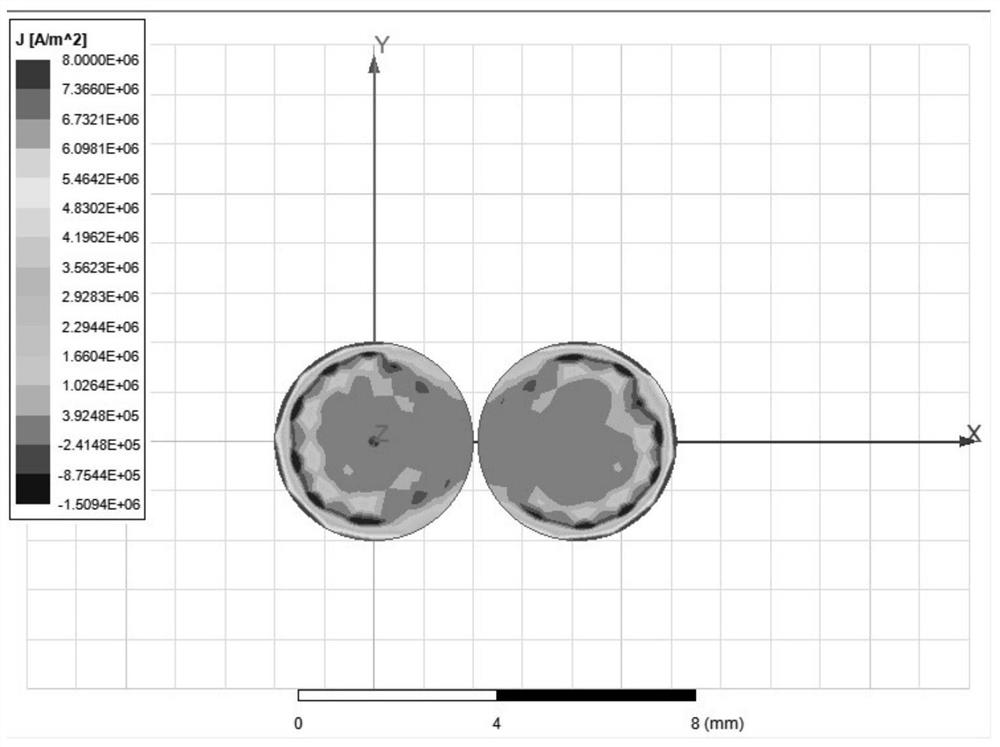
[0029] In order to reduce the influence of the proximity effect between the coils in the high-frequency working state, thereby reducing the AC internal resistance of the coils in the high-frequency working state, the coil of the present invention adopts the spiral winding method, and each turn of the coil forms a hollow circular shape Part of the section arc. Each turn of the coil is evenly arranged on the circumference of the ring, so that the magnetic fields between the conductors cancel each other to reduce the influence of the proximity effect on the coil internal resistance, and reduce the AC internal resistance of the coil at high frequencies. The specific mutual cancellation effect of the magnetic field generated between each turn of the coil, such as Figure 5 As shown, it can be seen that the coil adopts the space winding method in the present invention to make the current flow through the conductor more evenly, which can effectively reduce the loss caused by the proximity effect of the coil in the high-frequency working state, thereby reducing the coil in the high-frequency operation. AC internal resistance below. The coil of this special winding method is circular in any section, and the n turns of coils are evenly distributed on this circumference. From the mechanism generated by the proximity effect analyzed above, it can be seen that the magnetic fields generated by each turn of the coil under this uniform arrangement interact with each other. Cancellation allows the current to be evenly distributed in the conductor (e.g. Figure 5 shown, figure 1 and Figure 5 In contrast, the current is more evenly distributed due to the mutual cancellation of the magnetic fields), and the loss of the proximity effect is greatly reduced, thereby reducing the AC internal resistance of the coil at high frequencies.
[0030] To sum up, considering that the coil is affected by the skin effect and the proximity effect under the high frequency working state, the coil obtained by the winding method of the present invention has the effect of reducing the AC internal resistance of the coil as shown in Table 1 (N=18 turns ), it can be seen that the special winding method of this coil is effective in reducing the AC internal resistance of the coil at high frequencies.
[0031]
[0032]
[0033] Table 1
[0034]In the description of the present invention, it should be understood that the terms "middle", "length", "upper", "lower", "front", "rear", "vertical", "horizontal", "inner", The orientation or positional relationship indicated by "outer", "radial", "circumferential", etc. is based on the orientation or positional relationship shown in the drawings, and is only for the convenience of describing the present invention and simplifying the description, rather than indicating or implying that The device or element must have a specific orientation, be constructed and operated in a specific orientation, and therefore should not be construed as a limitation of the present invention.
[0035] In the present invention, unless otherwise expressly stated and defined, a first feature "on" a second feature may be in direct contact with the first and second features, or in indirect contact with the first and second features through an intermediary. "Plurality" means at least two, eg, two, three, etc., unless expressly specifically limited otherwise.
[0036] In the present invention, unless otherwise expressly specified and limited, terms such as "installation", "connection", "connection", "fixation" and other terms should be understood in a broad sense, for example, it may be a fixed connection or a detachable connection , or integrated; it can be a mechanical connection or an electrical connection or can communicate with each other; it can be directly connected or indirectly connected through an intermediate medium, it can be the internal connection of two components or the interaction relationship between the two components, unless otherwise expressly qualified. For those of ordinary skill in the art, the specific meanings of the above terms in the present invention can be understood according to specific situations.
[0037] The above is only to illustrate the embodiments of the present invention, and not intended to limit the present invention. For those skilled in the art, any modifications, equivalent replacements, and improvements made without creative work are within the spirit and principles of the present invention. etc., should be included within the protection scope of the present invention.

PUM

no PUM

Description & Claims & Application Information

We can also present the details of the Description, Claims and Application information to help users get a comprehensive understanding of the technical details of the patent, such as background art, summary of invention, brief description of drawings, description of embodiments, and other original content. On the other hand, users can also determine the specific scope of protection of the technology through the list of claims; as well as understand the changes in the life cycle of the technology with the presentation of the patent timeline. Login to view more.

Similar technology patents

Preparation method of litz wire suitable for high-frequency magnetic coupling wireless charging system

ActiveCN109616261BReduce skin effectReduce internal proximity effectsCable/conductor manufactureAc impedanceHigh frequency
Owner:HARBIN INST OF TECH

Flat wire winding, motor stator, and motor

PendingCN109301963AReduce skin effectSavings on winding materialMagnetic circuit stationary partsWindings conductor shape/form/constructionSkin effectStator
Owner:GREE ELECTRIC APPLIANCES INC OF ZHUHAI

Transmission line surge diversion grounding device

ActiveCN109616786AReduce skin effectThe surface current density is smallConnection contact member materialSkin effectPower equipment
Owner:STATE GRID SHANDONG ELECTRIC POWER +1

Novel busbar

PendingCN109390851AReduce thicknessReduce skin effectBus-bar/wiring layoutsBus-bar installationBusbarEngineering
Owner:ZHENJINAG KLOCKNER MOELLER ELECTRICAL SYST CO LTD

Classification and recommendation of technical efficacy words

  • Reduce skin effect

Large ampacity cable

Owner:ANHUI HUAXING CABLE GROUP

Method for winding dynamic analogue element by adopting stranded conductors

InactiveCN101615507AReduce skin effectMeet the simulation requirementsEducational modelsCoils manufactureSkin effectDynamic simulation
Owner:CHINA ELECTRIC POWER RES INST +1

Inductive coupling device and semiconductor processing device

ActiveCN111192812AReduce skin effectImproving Inductive Coupling Power Utilization EfficiencyElectric discharge tubesPhysicsHigh power density
Owner:BEIJING NAURA MICROELECTRONICS EQUIP CO LTD

High-frequency wire and manufacturing method thereof

InactiveCN106205839AEffective transpositionReduce skin effectInsulated cablesInsulated conductorsSkin effectEngineering
Owner:株洲市科达电机技术有限公司
Why Eureka
Try Eureka