Charging seat with high-precision centering terminals and motor vehicle

A charging stand, high-precision technology, applied in the direction of electric vehicles, charging stations, vehicle energy storage, etc., can solve problems such as temperature rise between terminals, fire and combustion in the charging system, and excessive contact resistance, so as to reduce the risk of fire and combustion , Improve corrosion resistance and improve service life

Pending Publication Date: 2021-11-26
CHANGCHUN JETTY AUTOMOTIVE PARTS CORP
View PDF0 Cites 2 Cited by
  • Summary
  • Abstract
  • Description
  • Claims
  • Application Information

AI Technical Summary

Problems solved by technology

[0002] With the increasing popularity of new energy vehicles, there are more and more supporting charging equipment and devices. However, accidents such as fire and spontaneous combustion continue to occur during the charging or discharging process of existing new energy vehicles. Most of the fires are caused by the high temperature rise in the process of power transmission, and the reason for the high temperature rise is that the contact resistance between the terminals of the charging equipment is too large, and the charging current is very large, and it will be at the contact position of the terminals. A sharp rise in temperature occurs, eventually causing the entire charging system to catch fire
[0003] Currently, the charging terminals in the charging stand on the market are generally female terminals. In order to facilitate installation during assembly, and to have a swaying margin to adapt to the insertion of the mating male terminal, the charging terminal in the charging stand and the installation side wall have a certain distance. gap, after the charging terminal in the charging stand is plugged into the mating terminal, it is easy to cause a small contact area between the terminals due to the lack of concentricity between the two, and the contact resistance is too high, which will cause the temperature rise between the terminals to be too high and eventually cause a fire

Method used


Image

  • Charging seat with high-precision centering terminals and motor vehicle
  • Charging seat with high-precision centering terminals and motor vehicle
  • Charging seat with high-precision centering terminals and motor vehicle

Examples


Embodiment 1

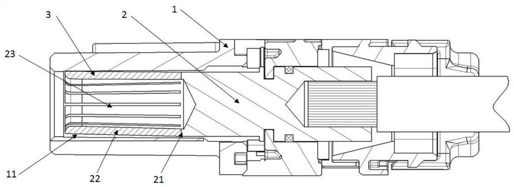
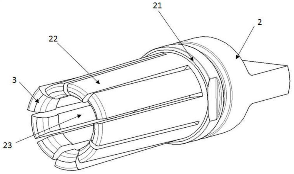
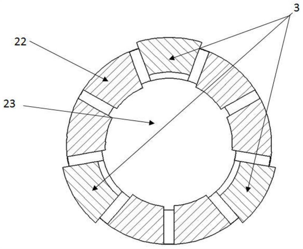
[0077] The present invention provides a charging stand 1 with high-precision centering of terminals, such as Figure 1-Figure 3 As shown, the charging base 1 is provided with a cavity 11 for accommodating the charging terminal 2. There is a gap between the inner peripheral wall of the cavity 11 and the outer peripheral wall of the charging terminal 2, and the supporting elastic piece 3 is arranged in the gap, and the supporting elastic piece 3 is arranged along the circumferential direction of the charging terminal 2. , the supporting elastic piece 3 is configured to limit the deviation of the axis of the charging terminal 2 from the axis of the cavity 11 . In the charging stand 1, the supporting elastic piece 3 is arranged in the circumferential direction of the charging terminal 2, which can support the charging terminal 2 in the center of the cavity of the charging stand 1, so that when the mating terminal is inserted, it can be directly plugged and contacted with the chargi...


PUM


Abstract

The invention provides a charging seat with high-precision centering terminals and a motor vehicle, the charging seat is provided with a cavity for accommodating a charging terminal, a gap exists between the inner peripheral wall of the cavity and the outer peripheral wall of the charging terminal, a supporting elastic piece is arranged in the gap, the supporting elastic piece is arranged along the circumferential direction of the charging terminal. The supporting elastic piece is configured to limit the axis of the charging terminal from deviating from the axis of the cavity. According to the charging seat, the matching terminals can be automatically centered at high precision, so that the matching terminals can be completely inserted and contacted, the contact resistance between the charging terminals and the matching terminals is reduced, the electrical performance of the charging seat is improved, the risk of fire and combustion during charging of the charging seat is reduced, and the service life of the charging seat is prolonged.

Description

technical field [0001] The invention relates to the technical field of charging, in particular to a charging stand with high-precision centering of terminals and a motor vehicle. Background technique [0002] With the increasing popularity of new energy vehicles, there are more and more supporting charging equipment and devices. However, accidents such as fire and spontaneous combustion continue to occur during the charging or discharging process of existing new energy vehicles. Most of the fires are caused by the high temperature rise in the process of power transmission, and the reason for the high temperature rise is that the contact resistance between the terminals of the charging equipment is too large, and the charging current is very large, and it will be at the contact position of the terminals. A sharp rise in temperature occurred, which eventually caused the entire charging system to catch fire. [0003] Currently, the charging terminals in the charging stand on t...

Claims


Application Information

Patent Timeline
Patent Type & Authority Applications(China)
IPC IPC(8): H01R13/40H01R13/03H01R13/11B60L53/16
CPCH01R13/40H01R13/03H01R13/11B60L53/16H01R2201/26Y02T10/70Y02T10/7072Y02T90/14
Inventor 王超王紫剑
Owner CHANGCHUN JETTY AUTOMOTIVE PARTS CORP
Why Eureka
Try Eureka