A kind of drying device and method for spraying the surface of bronze sculpture
A drying device and sculpture technology, which is applied to the surface coating liquid device, spraying device, liquid spraying device, etc., can solve the problems of uneven spraying, inconvenient cleaning, and single function of the drying device, so as to improve processing efficiency and facilitate Processing and use, processing effect is better
- Summary
- Abstract
- Description
- Claims
- Application Information
AI Technical Summary
Problems solved by technology
Method used
Image
Examples
Embodiment 1
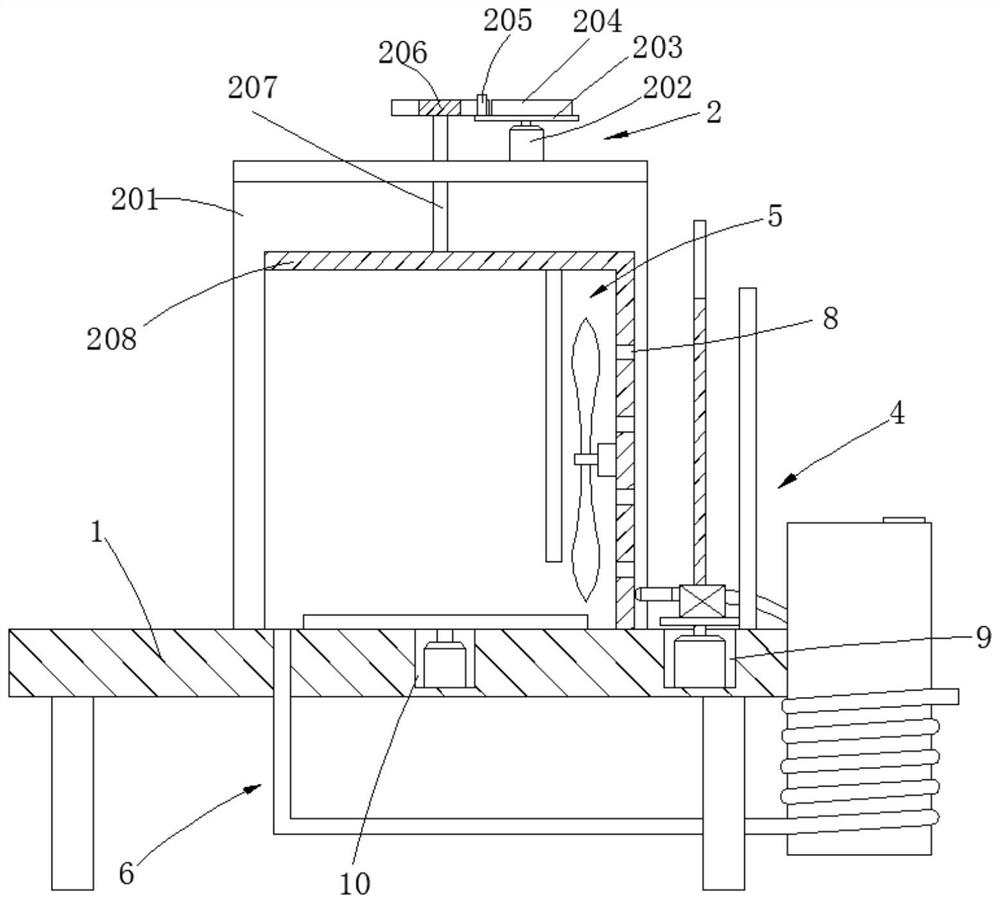
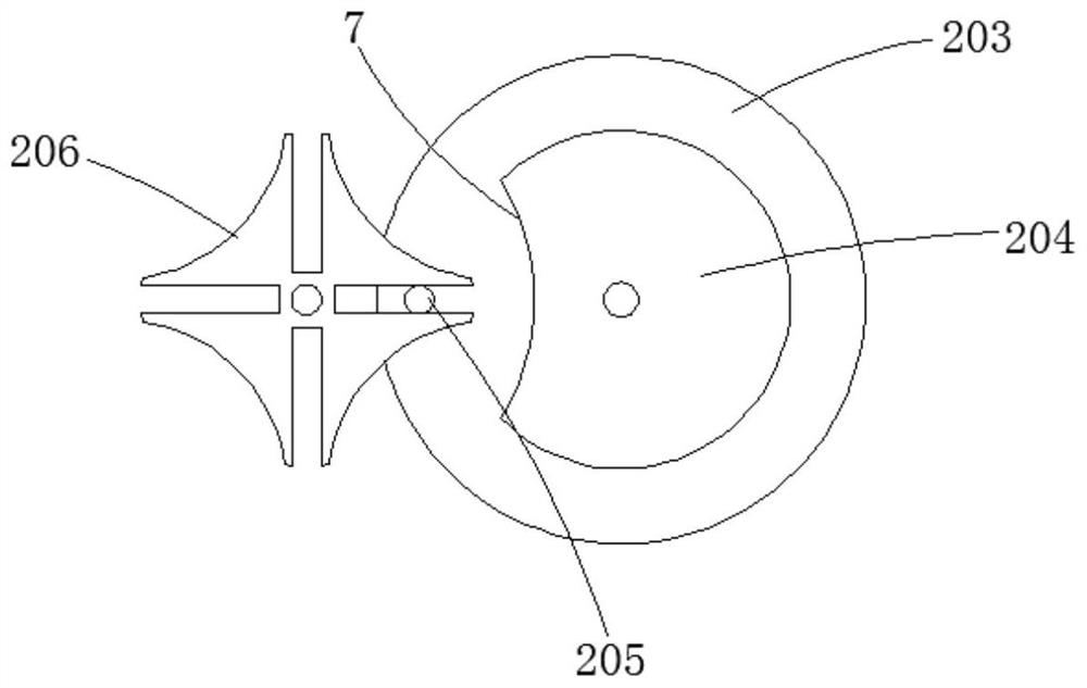
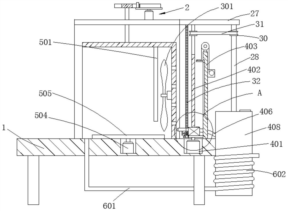
[0040] see Figure 1-8 , The present invention provides a technical solution: a drying device for spraying the surface of a bronze sculpture, comprising a processing table 1, a switching mechanism 2, a cleaning mechanism 3, a spraying mechanism 4, a drying mechanism 5 and a waste heat utilization mechanism 6, a switching mechanism It includes a bracket 201, a first motor 202, a chassis 203, a rotating block 204, a guide column 205, a sheave 206, a connecting rod 207 and a processing cover 208. The bracket 201 is fixedly connected to the top of the processing table 1, and the first motor 202 is installed on the bracket On the top of 201, the chassis 203 is fixedly connected to the output end of the first motor 202, the turning block 204 is fixedly connected to the top of the chassis 203, and coincides with the center position of the chassis 203, and one side of the turning block 204 is provided with an arc-shaped groove 7, The guide column 205 is fixedly connected to the top of...
Embodiment 2
[0046] Compared with Example 1, the difference is:
[0047] Among them, the top of the processing table is also provided with a dust collection mechanism. The dust collection mechanism includes a support rod 11, a first rotating rod 12, a fan blade 13, a first transmission belt 14, a connecting cylinder 15 and a collection bag 16. The processing table 1 is located in the motor slot. 10 A collection groove 17 is provided at the front side, a channel 18 is provided between the collection groove 17 and the motor groove 10, the support rod 11 is horizontally arranged between the inner walls of the collection groove 17, and the first rotating rod 12 is rotatably connected to the support rod 11. , the fan blade 13 is welded on the lower end of the first rotating rod 12, the first transmission belt 14 is sleeved between the first rotating rod 12 and the output shaft of the third motor 504, the connecting cylinder 15 is installed on the bottom of the collecting box 17, and the collecti...
Embodiment 3
[0049] Compared with Example 2, the difference is:
[0050] Among them, the limit plate 403 is also provided with an adjustment mechanism. The adjustment mechanism includes a retractor 19, a connecting rope 20, a guide wheel 21, a slider 22, a support plate 23 and a laser light 24. The retractor 19 is installed on the limit plate. On the right side of 403, the guide wheel 21 is installed on the top of the limit plate 403, the left side of the limit plate 403 is provided with a chute 25, the slider 22 is slidably connected in the chute 25, and the support plate 23 is fixed to the slider 22 Outside, one end of the connecting rope 20 is wound around the output end of the retractor 19, the other end passes through the guide wheel 21, and is fixed on the top surface of the support plate 23, the laser light 24 is installed on the top of the support plate 23, and The output end of the laser light 24 is located at one end away from the chute 25 , and the top connected to the pump 405 ...
PUM
 Abstract
Description
Claims
Application Information
 - R&D
- Intellectual Property
- Life Sciences
- Materials
- Tech Scout
- Unparalleled Data Quality
- Higher Quality Content
- 60% Fewer Hallucinations
Browse by: Latest US Patents, China's latest patents, Technical Efficacy Thesaurus, Application Domain, Technology Topic, Popular Technical Reports.
© 2025 PatSnap. All rights reserved.Legal|Privacy policy|Modern Slavery Act Transparency Statement|Sitemap|About US| Contact US: help@patsnap.com


