
Array substrate and manufacturing method thereof

An array substrate and manufacturing method technology, applied in the display field, can solve problems such as increasing the number of photomasks used, increasing manufacturing costs, and complicated manufacturing processes, so as to save production costs and production cycles, improve production yields, and connect and conduct performance Good results

Pending Publication Date: 2021-11-30
KUSN INFOVISION OPTOELECTRONICS
View PDF0 Cites 2 Cited by
  • Summary
  • Abstract
  • Description
  • Claims
  • Application Information

AI Technical Summary

Problems solved by technology

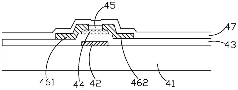
However, the ESL type TFT needs to add a photomask etching process when making the etching stopper layer 45, so the number of photomasks used is increased, the manufacturing cost is increased, and the manufacturing process is also relatively complicated, resulting in a decrease in production yield.
At the same time, the number of photomasks used in most of the current array substrate manufacturing processes is more than six, which greatly increases the manufacturing cost

Method used


Image

  • Array substrate and manufacturing method thereof
  • Array substrate and manufacturing method thereof
  • Array substrate and manufacturing method thereof

Examples


Embodiment Construction

[0052] The specific implementation manners of the present invention will be further described in detail below in conjunction with the accompanying drawings and embodiments. The following examples are used to illustrate the present invention, but are not intended to limit the scope of the present invention.

[0053] The terms "first", "second", "third", "fourth", etc. (if any) in the description and claims of the present invention are used to distinguish similar objects and not necessarily to describe specific sequence or sequence.

[0054] The up, down, left, right, front, back, top, bottom, etc. (if any) orientation words involved in the specification and claims of the present invention refer to the positions in the drawings of the structures in the drawings and the relationship between the structures. It is only defined for the clarity and convenience of expressing the technical solution. It should be understood that the use of location words should not limit the scope of ...


PUM


Abstract

The invention provides an array substrate and a manufacturing method thereof. The array substrate comprises a substrate; a first metal layer which is formed on the substrate and comprises a grid electrode and a scanning line, wherein the grid electrode is connected with the scanning line; a gate insulating layer which is formed on the substrate and covers the first metal layer; a second metal layer which is formed on the grid electrode insulating layer and comprises a source electrode and a data line, wherein the source electrode is connected with the data line, and the projection of the source electrode and the projection of the grid electrode on the array substrate are aligned or partially overlapped; and a metal oxide semiconductor layer which is formed on the gate insulation layer and comprises a pixel electrode and an active layer, wherein the pixel electrode is subjected to conductor treatment and is connected with the active layer, the active layer is connected with the source electrode, the source electrode is connected with the metal oxide semiconductor layer, and the active layer is correspondingly positioned over the source electrode and the grid electrode.

Description

technical field [0001] The present invention relates to the field of display technology, in particular to an array substrate and a manufacturing method thereof. Background technique [0002] With the continuous development of science and technology, the display technology has also developed rapidly. The thin film transistor TFT (Thin Film Transistor) technology has developed from the original a-Si (amorphous silicon) thin film transistor to the current LTPS (low temperature polysilicon) thin film transistor, Oxide (Metal oxide) thin film transistors, etc. Compared with low-temperature polysilicon TFTs and amorphous silicon TFTs, metal oxide TFTs have high electron mobility, high light transmittance, low leakage current, low deposition temperature, simple manufacturing process, and large area. Good uniformity, low manufacturing cost and other advantages. Wherein, the metal oxide TFT generally includes ESL (Etch Stop Layer, etch stop layer) type TFT and BCE (Back Channel Etch...

Claims


Application Information

Patent Timeline
Patent Type & Authority Applications(China)
IPC IPC(8): H01L21/77H01L27/12
CPCH01L27/1244H01L27/1225H01L27/1248H01L27/1259
Inventor 钟德镇蒋隽
Owner KUSN INFOVISION OPTOELECTRONICS
Learn More