Electronic apparatus and method for optimizing the use of motor-driven equipment in a control loop system

A control loop and equipment technology, applied in the field of optimizing the state of the control loop unit, can solve the problems such as the inability to effectively optimize the state of the control loop unit, and achieve the effects of improving reliability, reducing power consumption, and precise process control

Pending Publication Date: 2021-11-30
PEOPLEFLO MFG
View PDF9 Cites 2 Cited by
  • Summary
  • Abstract
  • Description
  • Claims
  • Application Information

AI Technical Summary

Problems solved by technology

Discenzo cannot effectively optimize the state of the control loop unit, which includes electric motors, working machines and final control elements installed in the control loop system

Method used


Image

  • Electronic apparatus and method for optimizing the use of motor-driven equipment in a control loop system
  • Electronic apparatus and method for optimizing the use of motor-driven equipment in a control loop system
  • Electronic apparatus and method for optimizing the use of motor-driven equipment in a control loop system

Examples


Embodiment Construction

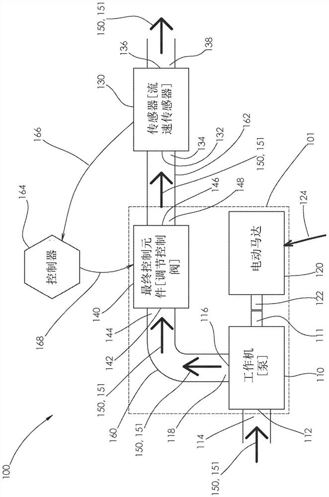
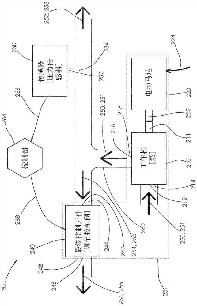
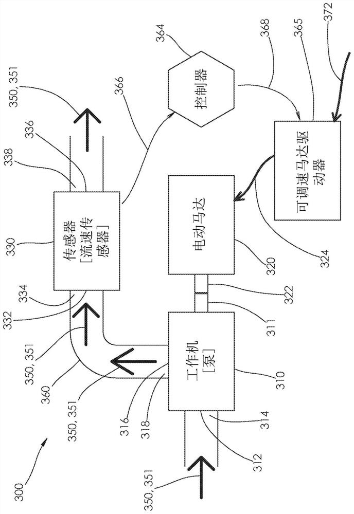
[0033] Figures 1-3 illustrate example embodiments of prior art process control loops, and it will be appreciated that an understanding of these process control loops is important to a proper understanding and appreciation of the present disclosure.

[0034] Figure 1 shows a first example implementation of a prior art control loop system (100), shown in a throttling control configuration. The control loop system (100) includes: a working machine (110), which in this embodiment includes a pump (such as a rotodynamic pump); an electric motor (120); a final control element (140) (such as a modulating control valve); a sensor (130), such as a flow rate sensor; and a process controller (164). The train (101) is defined as the three main machines in the control loop system (100), namely the pump (110), the motor (120) and the modulating control valve (140). The control loop system (100) further includes: tubing (160) connecting the pump outlet port (116) to the control valve inlet p...


PUM


Abstract

An apparatus and method to be implemented with a control loop system that includes machine set, wherein the machine set includes a working machine, an electric motor driving the working machine, and a final control element, and wherein the apparatus and method optimize the state of the machine set to minimize power consumption of the motor and maximize reliability of the machine set.

Description

[0001] Cross References to Related Applications [0002] This application claims the benefit of and priority to U.S. Patent Application No. 16 / 392,353, filed April 23, 2019, which is hereby incorporated by reference in its entirety. technical field [0003] The present invention relates generally to industrial process control loop systems, and more particularly to apparatus and methods for optimizing the state of a control loop assembly including electric motors, working machines, and final control elements installed in the control loop system. Background technique [0004] Control systems for industrial process applications include many control loops, which themselves include the physical and logical components necessary to perform the following four functions: 1) provide hydraulic or pneumatic energy to the system in the form of pressure and flow; 2) Measuring a process variable such as flow, pressure or temperature; 3) comparing the process variable measurement to the pro...

Claims


Application Information

Patent Timeline
Patent Type & Authority Applications(China)
IPC IPC(8): F04B17/03F04B49/06F04C15/00G05D7/06H02P7/00G06F9/44G06F1/32
CPCG05B13/0205F04B49/08F04B49/103F04B2203/0208H02P29/00F04D27/001F04D27/004F04D27/0261F04D27/002F04D27/0246F04D15/0066F04D15/0088F04D15/0022F05D2270/3061Y02B30/70F04C2240/81F04C28/28G05B13/021
Inventor W·R·布兰克梅尔M·P·汤普森
Owner PEOPLEFLO MFG
Why Eureka
Try Eureka