
Efficient oil-water separation waste liquid treatment method

A technology of oil-water separation and treatment method, which is applied in the direction of semi-permeable membrane separation, chemical instruments and methods, and immiscible liquid separation. The effect of storage cost reduction

Pending Publication Date: 2021-12-03
浙江零零零环境科技有限公司
View PDF0 Cites 0 Cited by
  • Summary
  • Abstract
  • Description
  • Claims
  • Application Information

AI Technical Summary

Problems solved by technology

General metalworking fluids include cutting fluids, cutting oils, stamping oils, quenching agents, high temperature oils, extreme pressure cutting fluids, grinding fluids, antirust oils, cleaning agents, etc. The impurity composition in the metal is complex, mainly containing metal particles and other impurity particles, and will dissolve some inorganic salt impurities. In order to reduce the oxidation and rust in the metal processing process, the metal processing fluid is usually made into an emulsion, and it will be used during use. Add water to dilute, so the post-treatment of metal processing waste liquid is more difficult. Usually, if waste liquid needs to be processed, it needs to be concentrated and then sent to a special processing institution for processing. The cost of storage and transportation is high, and there are additional costs. The cost of the treatment is relatively high for the enterprise. In order to reduce the cost of maintenance in the later period, it is necessary for the enterprise to adopt certain technical improvements to discharge the waste liquid to a certain extent, so as to reduce the post-treatment cost and reduce environmental pollution. Provide assistance for the technological upgrading and development of enterprises

Method used


Image

  • Efficient oil-water separation waste liquid treatment method

Examples


Embodiment Construction

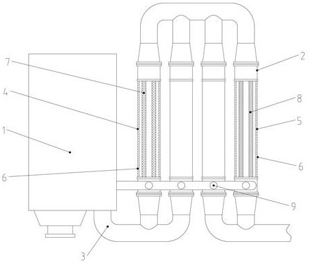
[0016] The present invention will be further described in detail below in conjunction with the accompanying drawings and examples. The following examples are explanations of the present invention and the present invention is not limited to the following examples.

[0017] A treatment method for high-efficiency oil-water separation waste liquid. After the waste liquid is produced in the production process, it is diverted and transported to a collection container through a pipeline. In this state, the solid particles sink to the bottom, the oily liquid floats up to form the top layer, and the rest of the middle part is an aqueous solution. The oily liquid on the top layer is separately diverted and discharged and concentrated, and the middle aqueous solution is diverted to the circulation purification device. The proportion of water content is ≥85%, the mass proportion of solid particles is ≤5%, and the mass proportion of oily liquid is ≤10%.

[0018] The circulation purificatio...


PUM


Abstract

The invention provides an efficient oil-water separation waste liquid treatment method, which comprises the following steps: after being produced in the production process, the waste liquid is guided and conveyed into a collection container through a pipeline, the waste liquid slowly flows in the collection container to stand, solid particles sink to the bottom when the waste liquid is in the standing state, oily liquid floats to the top layer, the left middle part is an aqueous solution, the oily liquid on the top layer is independently guided, discharged and concentrated, the aqueous solution on the middle layer is guided into a circulating purification device, the water content of the aqueous solution is larger than or equal to 85%, the mass ratio of solid particles is smaller than or equal to 5%, the mass ratio of the oily liquid is smaller than or equal to 10%, the aqueous solution generates purified water in the circulating purification device, the rest part is circularly filtered, and the final high-concentration waste liquid is intensively collected. According to the scheme, the filtering effect of the waste liquid is improved by adopting a mode of early-stage standing and circulating purification.

Description

technical field [0001] The invention relates to a high-efficiency recovery and treatment device for waste liquid in the production and processing process, in particular to a treatment method for high-efficiency oil-water separation waste liquid. Background technique [0002] Metalworking fluid is a functional liquid used in the metalworking process. The waste of the processing fluid produced after use is waste liquid. The composition of the waste liquid is complex, and there are many types of metalworking fluids. Lubricating and cooling, as well as anti-rust cleaning and other functions. General metalworking fluids include cutting fluids, cutting oils, stamping oils, quenching agents, high temperature oils, extreme pressure cutting fluids, grinding fluids, antirust oils, cleaning agents, etc. The impurity composition in the metal is complex, mainly containing metal particles and other impurity particles, and will dissolve some inorganic salt impurities. In order to reduce t...

Claims


Application Information

Patent Timeline
Patent Type & Authority Applications(China)
IPC IPC(8): B01D17/02B01D63/00
CPCB01D17/02B01D63/00
Inventor 唐谊平陈强张健力金杨福徐登波沈华郑忠斌
Owner 浙江零零零环境科技有限公司
Learn More